

Yes, surface finishing can affect the final dimensions and tolerances of CNC machined parts. Plating and coating add material, while polishing and abrasive finishing remove material. The amount of change depends on the process, coating thickness, part geometry, and the location of critical features.
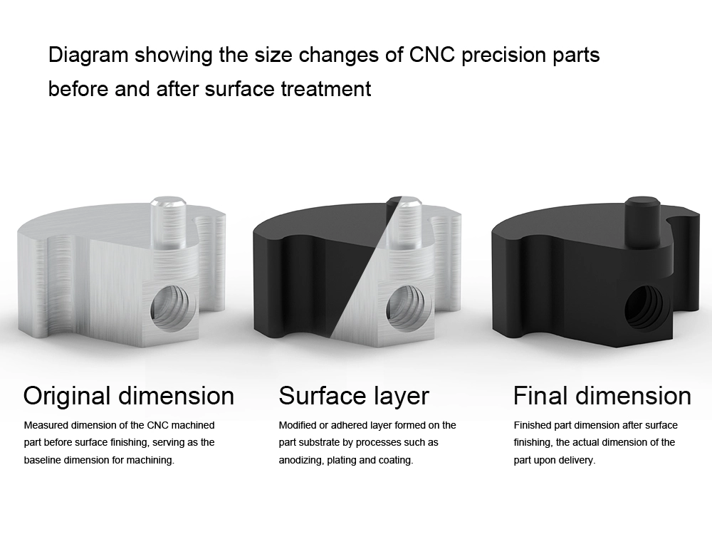
Yes, surface finishing can change the final dimensions and tolerances of CNC machined parts. The reason is that surface finishing is not always a purely cosmetic process. Some finishing methods add a new layer of material, some remove material from the original surface, and others transform the outer layer of the base material into a new protective structure.
The dimensional effect depends on the type of surface treatment and how much the process changes the physical boundary of the machined feature. For example, plating and powder coating increase part dimensions by adding material to the surface, while polishing and grinding may reduce dimensions by removing small amounts of material. Anodizing follows a different mechanism because it converts part of the aluminum surface into an oxide layer that changes the original surface boundary.
These dimensional changes become especially important for precision CNC features such as:
The key point is that the final dimension of a CNC part is determined not only by machining accuracy but also by the effect of the selected surface finishing process. Engineers should consider the finishing process as part of the overall manufacturing sequence to ensure the final component meets its functional requirements.
In general, surface finishing changes CNC dimensions through three main mechanisms:
Material addition
Processes such as electroplating and powder coating create an additional layer on the surface, increasing external dimensions and reducing internal clearances.
Material removal
Processes such as polishing and grinding remove surface material, which may reduce dimensions if the removal amount is not carefully controlled.
Surface conversion
Processes such as anodizing chemically transform the surface layer of the base material, creating a new protective layer that can influence final feature dimensions.
Understanding these mechanisms helps engineers select suitable finishing processes and avoid tolerance issues during final assembly or inspection. Surface finishing should therefore be considered together with machining tolerances, functional requirements, and final application conditions rather than treated as a separate post-processing step.
Surface finish, surface roughness, and dimensional tolerance describe different aspects of CNC part quality and should not be treated as the same requirement. Surface finish defines the final surface condition, surface roughness describes microscopic surface texture, and dimensional tolerance specifies the acceptable variation in part size and geometry.
These terms are often used together in CNC drawings and manufacturing discussions, which can create confusion during design and inspection. However, each one controls a different performance factor. A part can have a smooth surface but still be outside its required dimensional tolerance, or it can meet dimensional requirements while having a surface texture that is unsuitable for a specific application.
Quality characteristic | What it describes | Common specifications | Main purpose |
Surface finish | The final condition or treatment applied to a CNC surface | Anodized, plated, polished, passivated | Improve corrosion resistance, wear resistance, appearance, or surface performance |
Surface roughness | Microscopic variations and irregularities on the surface | Ra, Rz (μm) | Control friction, sealing, wear, and contact behavior |
Dimensional tolerance | Allowed variation in size and geometry | ±0.01 mm, H7, position tolerance | Ensure proper fit, assembly, and functional accuracy |
Surface Finish: The Final Surface Condition
Surface finish refers to the final state of a CNC part after machining and any additional treatment processes. It includes processes such as anodizing, plating, powder coating, polishing, and passivation.
The purpose of a surface finish is usually related to improving specific properties rather than directly defining dimensional accuracy. For example, anodizing may improve corrosion resistance and surface hardness, while plating may provide wear resistance or additional protection against environmental conditions.
However, a surface finish specification alone does not confirm that a component will assemble correctly. A drawing requirement such as “hard anodized aluminum” identifies the required treatment but does not indicate whether a precision bore, threaded hole, or mating surface remains within its required size after processing.
Surface Roughness: The Microscopic Surface Texture
Surface roughness describes small-scale surface variations created during machining or finishing. It is commonly measured using parameters such as Ra and Rz.
A lower Ra value generally indicates a smoother surface, which may be important for applications involving:
However, surface roughness does not directly represent dimensional accuracy. A polishing process may produce a very smooth surface while removing too much material and causing the feature size to move outside the required tolerance range.
Dimensional Tolerance: The Control of Size and Geometry
Dimensional tolerance defines how much a manufactured feature is allowed to deviate from its specified dimensions. It applies to critical measurements such as:
For example, a bearing bore may require a tight diameter tolerance to ensure proper installation, while the same surface may also require a specific roughness value to achieve reliable operation. These two requirements must be controlled separately because they describe different characteristics.
The relationship between these three concepts can be summarized as:
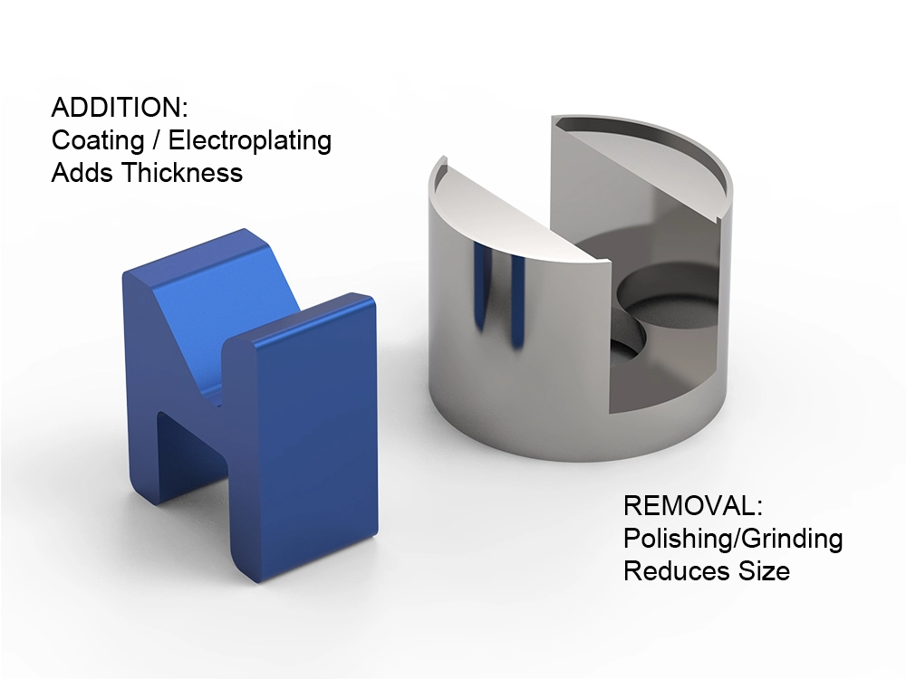
Surface finishing changes CNC part dimensions when the process adds material to the surface, removes material from the part, or creates a conversion layer with a measurable thickness. Although many finishing processes only affect the outermost layer of a component, even a small change can become significant when the required machining tolerance is tight.
The basic relationship between machining and finishing can be expressed as:
Final dimension = Machined dimension + coating buildup − material removed
This means the final size of a CNC feature is not determined only by the machining operation. The selected surface finishing process also affects the final functional boundary of the part.
Adding Material: Coating and Plating Increase Dimensions
Processes such as electroplating and powder coating increase part dimensions because they create an additional layer on the original surface.
For external features:
For internal features:
For example, if a coating thickness is 10 μm on each side of a bore, the effective bore diameter may decrease by approximately 20 μm before considering process variation. The actual dimensional change depends on coating uniformity, geometry, and process control.
Removing Material: Polishing and Grinding Reduce Dimensions
Processes such as polishing and grinding change dimensions by removing material from the surface. These processes are commonly used to improve surface quality, remove defects, or achieve specific surface conditions.
However, uncontrolled material removal may cause:
For precision components, polishing and grinding should be treated as controlled material removal processes rather than simple appearance improvements.
Conversion Layers: Anodizing Changes the Surface Boundary
Anodizing creates a protective oxide layer by converting part of the base material into a new surface structure. Unlike plating, which deposits additional material, anodizing changes the original aluminum surface through a chemical conversion process.
The dimensional impact depends on:
Features with limited clearance, such as precision holes, threads, and bearing seats, are more sensitive because even small dimensional changes can affect their function.
Factors That Influence Final Dimensional Change
The actual dimensional change after surface finishing is affected by more than the nominal process specification. Important factors include:
Factor | Influence on dimensions |
Coating thickness | Determines how much material is added or transformed |
Thickness uniformity | Causes local dimensional variation |
Part geometry | Complex areas may experience uneven treatment |
Surface preparation | Affects coating or conversion layer formation |
Process control | Determines repeatability between production batches |
Therefore, engineers should evaluate surface finishing effects before production begins, especially for components with tight tolerances. The finishing process, machining allowance, and final functional dimensions should be considered together to ensure the completed CNC part meets its design requirements.
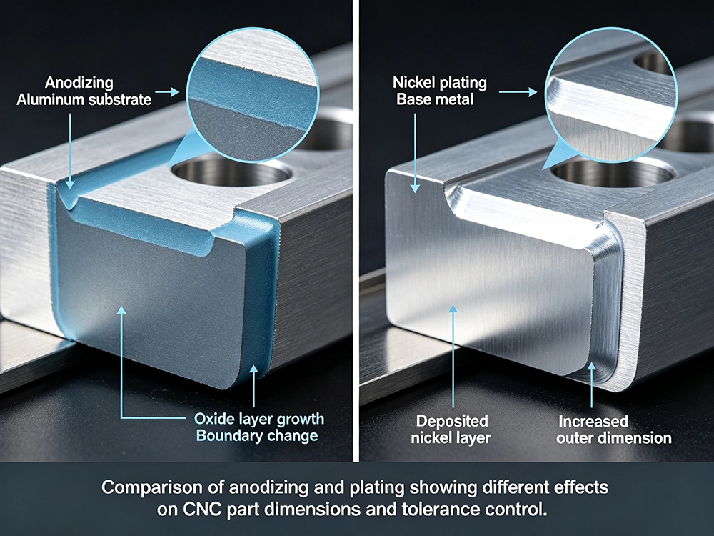
Anodizing and plating affect CNC machining tolerances because both processes create a surface layer that changes the final boundary of machined features. However, the two processes work through different mechanisms: anodizing converts the surface layer of the base material into an oxide structure, while plating deposits additional material onto the part surface.
For precision CNC components, these differences are important because the resulting surface layer can influence the fit and function of:
The dimensional risk is mainly determined by layer thickness, thickness distribution, part geometry, and the tolerance available for the finished feature.
Feature | Anodizing | Plating |
Process mechanism | Converts part of the substrate into an oxide layer | Deposits a separate metallic layer onto the surface |
Common materials | Aluminum alloys | Steel, stainless steel, aluminum, copper alloys, and other metals |
Main dimensional effect | Changes the surface boundary through oxide growth | Increases dimensions through coating buildup |
Typical tolerance concerns | Bore size, thread clearance, bearing fits | Shaft diameter, hole clearance, thread engagement |
Common control methods | Thickness control, masking, post-treatment inspection | Coating thickness control, masking, allowance machining, post-plating finishing |
Anodizing affects aluminum CNC part dimensions because the oxide layer is formed by converting the aluminum surface into aluminum oxide. Unlike a traditional coating that simply sits on top of the substrate, anodizing changes part of the original material structure and extends beyond the original machined boundary.
The dimensional effect depends on:
Standard anodizing usually creates a thinner surface layer, while hard anodizing produces a thicker and more wear-resistant oxide layer. Because of this, hard anodizing typically requires greater consideration when machining precision features.
The most sensitive areas include:
Precision bores: oxide growth may reduce the effective hole diameter.
Threaded holes: reduced clearance may affect fastener installation.
Bearing seats: dimensional changes may influence press fits and alignment.
Mating surfaces: surface buildup may affect assembly relationships.
For these applications, engineers commonly use:
The important point is that anodizing requirements should be considered together with the final functional dimensions. A part that meets tolerance before anodizing may no longer meet the required fit after the oxide layer is formed.
Nickel plating affects CNC tolerances because deposited nickel creates an additional metallic layer on the surface of the part. This buildup changes the final dimensions of both external and internal features.
Unlike anodizing, where the surface is converted into an oxide layer, nickel plating adds material directly to the component. Therefore, the dimensional change is mainly controlled by:
Typical dimensional effects include:
Complex geometries can create uneven plating thickness because current distribution is not always uniform across the entire part. Sharp edges, recessed areas, internal corners, and deep holes may experience different coating buildup compared with flat surfaces.
To control nickel plating effects, manufacturers may use:
For example, a precision shaft that requires a specific final diameter may be machined slightly undersize before plating. After the nickel layer is applied, the finished shaft can reach the required dimension.
When nickel plating is selected for precision CNC parts, machining capability and finishing control should be considered together through custom electroplating for machined parts (Custom Electroplating Solutions for Corrosion Resistance). This ensures the coating provides corrosion and wear protection without compromising dimensional accuracy.
Different surface finishing processes affect CNC part accuracy in different ways because some processes add material, some remove material, and others mainly modify the surface properties without creating a significant dimensional layer. Selecting the appropriate finishing method requires balancing functional requirements, surface performance, and allowable dimensional change.
The dimensional risk of a finishing process depends on how much it changes the physical geometry of the part and whether the affected surfaces are functionally important.
Surface finishing process | Dimensional effect | Main purpose | Dimensional risk level |
Powder coating | Increases dimensions | Corrosion protection, durability, appearance | High |
Polishing | Reduces dimensions | Improves smoothness and surface appearance | Medium |
Mass finishing | Reduces dimensions and rounds edges | Deburring and surface improvement for batches of parts | Medium |
Passivation | Usually minimal dimensional change | Improves corrosion resistance of stainless steel | Low |
Powder coating affects CNC part accuracy because it creates a relatively thick protective layer on the surface. Compared with thin conversion treatments, powder coating usually introduces a more noticeable dimensional change.
The additional coating thickness may affect:
For example, coating buildup inside a threaded hole can reduce the available thread clearance and make fastener installation more difficult. Similarly, coating on a precision mating surface may interfere with component alignment.
To control powder coating effects, engineers should define:
For components with tight fits, critical surfaces are often masked before coating to prevent unwanted dimensional changes.
Polishing improves surface smoothness by removing small amounts of material through abrasive action. It is widely used when low surface roughness, improved appearance, or reduced friction is required.
However, polishing does not automatically improve dimensional accuracy. The amount of material removed depends on:
For precision CNC components, polishing should be controlled as a material-removal process. The allowable polishing allowance should be considered during machining to ensure the final dimensions remain within tolerance.
Mass finishing processes, such as tumbling and vibratory finishing, are commonly used for large quantities of CNC parts to remove burrs, smooth edges, and improve surface consistency.
Although effective for improving general surface quality, mass finishing can influence dimensional accuracy when processing time is excessive or when parts contain small precision features.
Potential effects include:
Features such as small holes, thin walls, and sharp edges require additional attention because they are more sensitive to abrasive removal.
To maintain accuracy, manufacturers should control:
Passivation usually has a limited effect on CNC dimensions because it is a chemical surface treatment rather than a thick coating process. It is commonly applied to stainless steel components where corrosion resistance is required without significantly changing part geometry.
Compared with plating or powder coating, passivation generally creates a much smaller dimensional risk. However, manufacturers should still verify:
In summary, coating processes such as powder coating mainly create dimensional growth, while abrasive processes such as polishing and mass finishing may reduce dimensions through material removal. Passivation provides corrosion protection with minimal geometric impact, making it suitable for precision stainless steel components where dimensional stability is important.
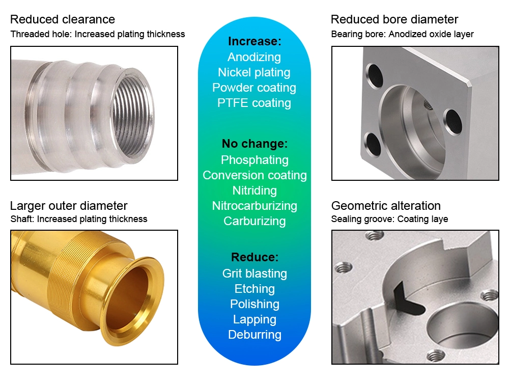
Not all surfaces on a CNC machined part require the same level of finishing control. However, functional features with tight fits, sealing requirements, or positioning requirements need special surface finish control because even small dimensional changes can affect assembly performance and reliability.
Surface finishing decisions should therefore be based on how each feature functions rather than applying the same treatment to every area of the component. Critical features should be identified before finishing so manufacturers can determine whether masking, dimensional compensation, or post-treatment inspection is required.
CNC feature | Potential issue after surface finishing | Functional impact | Recommended control |
Threaded holes | Coating buildup reduces thread clearance | Difficult assembly or incomplete fastener engagement | Mask threads, control coating thickness, or perform post-treatment machining |
Bearing bores | Reduced bore size changes fit conditions | Bearing installation problems and alignment errors | Reserve finishing allowance or inspect bore dimensions after treatment |
Precision shafts | Increased diameter affects clearance | Improper shaft-to-hole fit and increased friction | Mask functional surfaces or perform final grinding |
Sealing grooves | Coating changes groove geometry | Incorrect seal compression and possible leakage | Control coating thickness and verify final dimensions |
Datum surfaces | Surface changes affect measurement references | Reduced positioning accuracy during assembly | Protect datum areas and inspect after finishing |
Electrical contact surfaces | Surface treatment changes contact properties | Increased resistance or unreliable connections | Specify functional coating requirements |
Threaded Holes: Protecting Assembly Accuracy
Threaded features are among the most sensitive CNC features because their functional clearance is limited. A coating layer that appears insignificant on a flat surface can create interference when applied inside threads.
For example, plating or powder coating inside a threaded hole may reduce the effective thread diameter and prevent proper fastener engagement. In some applications, excessive buildup may cause thread damage during assembly.
Common control methods include:
Bearing Bores: Maintaining Precision Fits
Bearing bores require strict dimensional control because the relationship between the bearing and the housing determines mechanical performance. Surface finishing processes that reduce bore size or increase surface thickness can change the intended fit.
Potential issues include:
For bearing-related features, engineers should define the final bore requirement after finishing rather than relying only on the pre-treatment machining dimension.
Sealing Grooves: Controlling Surface Changes
Sealing features such as O-ring grooves and gasket surfaces are highly sensitive to dimensional changes because their performance depends on accurate geometry and controlled contact conditions.
Surface treatment can affect:
For these applications, controlling coating thickness and verifying final dimensions are often more important than achieving a specific visual appearance.
Datum Surfaces: Maintaining Reference Accuracy
Datum surfaces provide the reference points used for machining, inspection, and assembly. If these surfaces are affected by uneven coating buildup or material removal, the measured position of other features may also be affected.
For precision components, manufacturers may:
Electrical Contact Areas: Controlling Functional Surface Properties
Electrical contact surfaces require special consideration because surface treatments can influence conductivity, contact resistance, and long-term reliability.
Depending on the application, engineers may need to specify:
By identifying critical CNC features before surface finishing, manufacturers can select the appropriate process controls and avoid tolerance failures. The goal is not to minimize all surface treatment effects, but to ensure that each functional feature receives the correct level of protection and dimensional control.
CNC drawings should clearly define whether critical dimensions apply before or after surface finishing, because finishing processes can change the final functional dimensions of machined features. Without this clarification, manufacturers may produce parts that meet the machining requirements before treatment but fail to assemble or perform correctly after finishing.
The most important principle is that dimensions affecting fit and function should be controlled in the final finished condition. If a surface treatment changes the boundary of a feature, the post-finish dimension represents the actual condition that determines whether the component will work as intended.
For example:
A complete surface finishing specification should include more than only the treatment type. To avoid dimensional conflicts, CNC drawings should define:
Drawing requirement | Purpose |
Specifies the required process, such as anodizing, plating, powder coating, or passivation | |
Coating or layer thickness | Defines the expected amount of surface buildup or conversion layer growth |
Critical dimensions after finishing | Ensures functional features meet final requirements |
Masking requirements | Protects surfaces that must remain untreated |
Surface roughness requirements | Defines Ra/Rz values independently from dimensional accuracy |
Inspection requirements | Specifies how the finished part should be verified |
A clear drawing specification may look like:
Material: Aluminum 6061-T6
Finish: Hard anodizing, 25 ± 5 μm
Critical bore: Ø20.000 +0.015 / 0 mm after anodizing
Masking required: Bore and threaded holes
Surface roughness: Ra 1.6 μm maximum
This information tells the manufacturer that the bore dimension must be achieved after anodizing, not before the treatment process.
One common manufacturing problem occurs when machining and finishing requirements are interpreted separately. A machining supplier may inspect the component before treatment, while the customer evaluates the final finished part after coating or anodizing.
Without a clear drawing requirement, both parties may consider their measurements correct, even though the final component does not meet the assembly requirement.
For precision CNC parts, engineers should avoid relying on general notes such as:
These instructions identify the process but do not define the final dimensional condition.
Instead, drawings should specify:
It is also important to separate surface treatment specifications from dimensional requirements.
For example:
A part can meet its coating thickness requirement but still fail its dimensional tolerance. Likewise, a part can achieve a low Ra value but have incorrect hole size or position.
Clear separation of these requirements allows manufacturers to select the correct machining allowance, finishing process, and inspection method. For complex precision components, following established CNC machining tolerance standards (CNC Machining Tolerance Standards) helps ensure that surface finishing improves part performance without causing unexpected assembly issues.
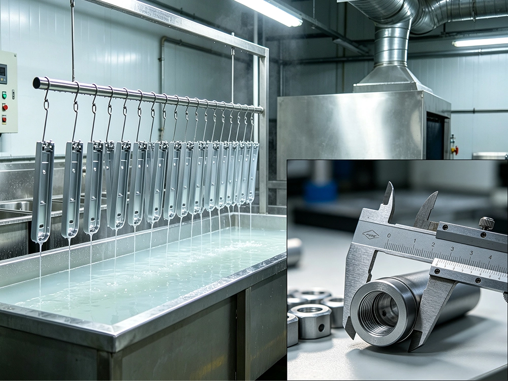
Surface finish and CNC tolerances require different inspection methods because they represent different aspects of part quality. Dimensional accuracy, surface roughness, coating thickness, and geometric accuracy cannot be evaluated using the same measurement method.
A reliable inspection process uses the appropriate equipment for each requirement. Measuring only the final dimensions is not enough because a CNC part may meet its size tolerance while failing surface requirements, or achieve excellent surface quality while exceeding dimensional limits.
Inspection item | Common measurement equipment | What it verifies |
Dimensional size | Micrometer, caliper, bore gauge, height gauge | External diameter, hole size, thickness, length |
Geometric tolerance | Coordinate Measuring Machine (CMM) | Position, flatness, roundness, alignment, profile accuracy |
Surface roughness | Surface roughness tester | Ra, Rz, and microscopic surface texture |
Coating thickness | Coating thickness gauge | Plating thickness and surface layer thickness |
Visual appearance | Visual inspection and comparison standards | Color consistency, scratches, surface defects |
Measuring Dimensional Accuracy After Surface Finishing
Dimensional inspection confirms whether the finished CNC component remains within the specified size and geometry requirements after all processing steps are completed.
Common measurement tools include:
For simple features, traditional precision instruments may be sufficient. However, components with multiple precision surfaces often require coordinate measurement to verify the relationship between features.
For example, a plated component may maintain the correct shaft diameter but still fail because the shaft position, concentricity, or alignment has changed beyond the allowable tolerance.
Measuring Surface Roughness (Ra and Rz)
Surface roughness measurement evaluates microscopic surface variations rather than overall part dimensions. The most common parameters are:
Ra: Average roughness value of the surface profile
Rz: Maximum height difference between surface peaks and valleys
Surface roughness measurement is important for applications involving:
However, roughness measurement cannot replace dimensional inspection. A surface roughness tester can confirm that a surface meets its Ra requirement, but it cannot determine whether a bore diameter, shaft size, or feature position is correct.
Measuring Coating and Surface Layer Thickness
For processes such as plating and anodizing, coating thickness measurement is essential because the added or converted surface layer directly affects final dimensions.
Coating thickness inspection helps verify:
For example, a nickel-plated precision shaft may require a controlled coating thickness to achieve corrosion resistance while maintaining the final diameter tolerance.
Combining Inspection Methods for Final Quality Control
Because CNC surface finishing affects multiple quality characteristics, final inspection should combine different measurement methods according to the part requirements.
A typical post-finishing inspection process may include:
For complex precision components, manufacturers often rely on professional CNC measuring and inspection equipment (CNC Measuring Tools and Equipments) to verify dimensions, surface conditions, and geometric accuracy after finishing.
The goal of inspection is not only to confirm that a part looks correct, but to ensure that the finished component maintains the required fit, function, and performance throughout its intended application.
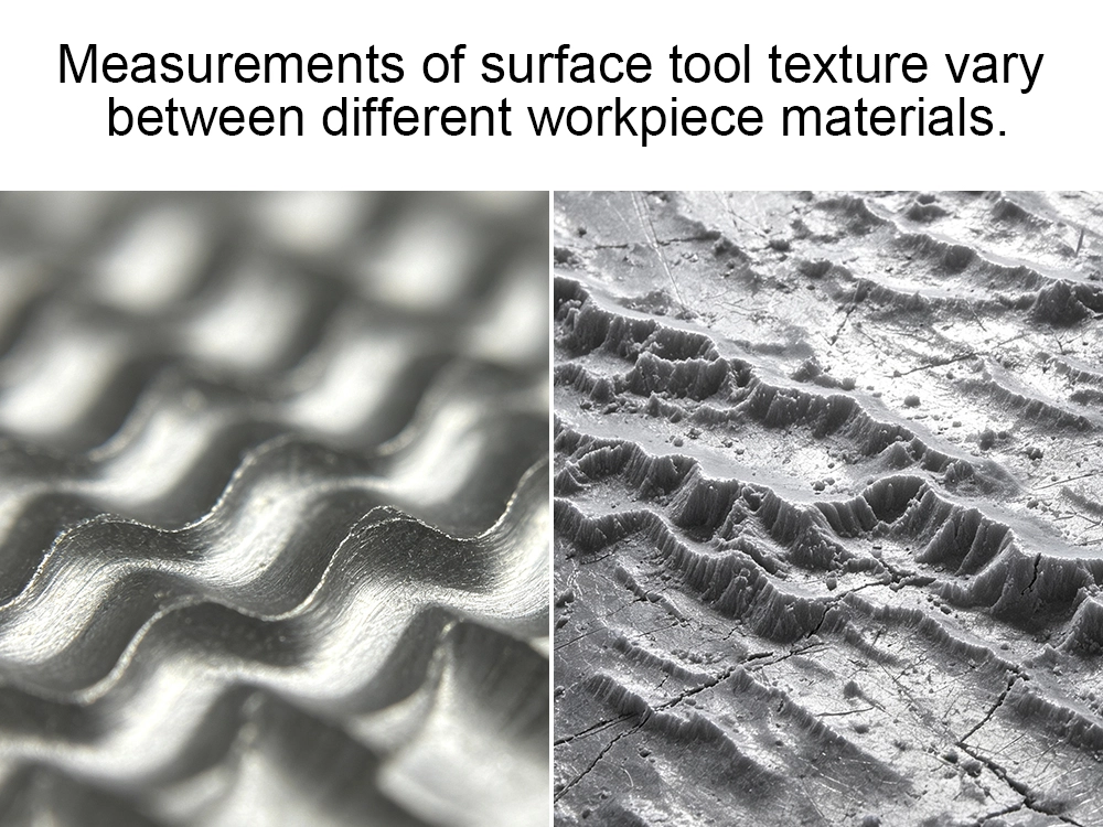
No, a smoother surface does not automatically mean a more accurate CNC part because surface roughness and dimensional tolerance measure different aspects of manufacturing quality. Surface roughness describes microscopic surface texture, while dimensional tolerance defines the allowable variation in the size and geometry of a component.
This distinction is important because a common misunderstanding in CNC manufacturing is assuming that a lower Ra value always indicates higher precision. In reality, surface smoothness and dimensional accuracy are independent requirements that must be controlled separately.
Comparison factor | Surface roughness | Dimensional tolerance |
Definition | Measures microscopic surface irregularities | Defines acceptable variation in part size and geometry |
Common parameters | Ra, Rz (μm) | ± tolerance, tolerance grade, geometric tolerance |
Measurement method | Surface roughness tester | Micrometer, bore gauge, CMM |
Main purpose | Control friction, sealing, wear, and surface behavior | Ensure fit, assembly accuracy, and functional performance |
Influenced by | Machining method and finishing process | Machining accuracy, process control, and geometry |
Processes such as polishing, grinding, and fine machining can significantly improve surface smoothness by reducing microscopic irregularities. However, these processes may also remove material from the part surface.
If material removal is not carefully controlled, the component may experience:
For example, a polished shaft may achieve a very low Ra value and appear highly refined, but excessive polishing could reduce its diameter and cause clearance problems when assembled with another component.
In this case:
Surface quality improves.
Dimensional accuracy may decrease.
Therefore, a smoother surface does not necessarily indicate a more precise CNC component.
The opposite situation can also occur. A CNC part may meet all dimensional requirements but still have a surface condition that is unsuitable for its application.
For example:
Surface roughness and dimensional tolerance should be specified separately on CNC drawings.
A complete requirement may include:
These specifications communicate that both the physical size and surface condition are important, but they are controlled through different processes and inspection methods.
The relationship can be summarized as:
Understanding this distinction helps engineers avoid over-specifying finishes or assuming that a smoother CNC surface automatically provides better dimensional accuracy. For precision applications, the machining process, surface treatment, and inspection strategy must be considered together to achieve the required final performance.
The best surface finish for a CNC part depends on the material, operating environment, functional requirements, appearance expectations, and allowable dimensional change. There is no single finishing process that is suitable for every application because different treatments provide different advantages in corrosion resistance, wear performance, surface quality, electrical properties, and dimensional stability.
Engineers should select a surface finishing process by balancing two key factors:
What performance improvement does the part require?
How much dimensional change can the part tolerate after finishing?
A finish that improves corrosion resistance or durability may introduce dimensional risks, while a process that has minimal dimensional impact may not provide sufficient protection for harsh operating conditions.
Application requirement | Recommended finishing process | Why it is suitable |
Aluminum corrosion protection and appearance improvement | Anodizing | Creates a protective oxide layer and provides color options |
Wear resistance for mechanical components | Nickel plating or chrome plating | Adds a durable surface layer with improved wear performance |
Steel corrosion protection | Zinc plating or black oxide | Provides corrosion resistance with controlled surface modification |
Stainless steel corrosion resistance | Passivation | Improves corrosion resistance without significant dimensional change |
Low roughness and improved appearance | Polishing or electropolishing | Reduces surface irregularities and improves surface quality |
Precision mating components | Masking, thin coatings, or post-finishing machining | Minimizes dimensional impact on critical features |
Step 1: Define the Functional Requirement
The first step in selecting a surface finish is understanding what the component needs to achieve during operation.
Different applications prioritize different properties:
Corrosion resistance: Components exposed to moisture, chemicals, or outdoor environments may require anodizing, plating, or passivation.
Wear resistance: Moving or high-friction components may benefit from harder surface layers such as nickel or chrome plating.
Low friction and smooth contact: Sliding components may require polishing or controlled surface finishing.
Appearance improvement: Consumer-facing components may prioritize color, texture, and visual consistency.
Dimensional stability: Precision assemblies may require treatments with minimal thickness variation.
The finishing process should be selected according to the actual function of the CNC part rather than based only on appearance.
Step 2: Evaluate Allowable Dimensional Change
After identifying the required performance, engineers should evaluate how much dimensional variation the finishing process may introduce.
Processes that add material, such as:
Processes that remove material, such as:
Polishing
Grinding
require control of:
For precision CNC components, the allowable dimensional change should be defined before selecting the finishing process.
Step 3: Match the Finish to the Material
Material compatibility is another important factor in surface finish selection.
Common examples include:
Aluminum alloys: Often treated with anodizing because the oxide layer improves corrosion resistance and surface hardness.
Steel components: Commonly use plating or conversion coatings to improve corrosion resistance and durability.
Stainless steel parts: Frequently use passivation because it enhances corrosion resistance while maintaining dimensional stability.
Choosing an unsuitable finishing process may increase manufacturing complexity or create unnecessary tolerance risks.
Step 4: Consider Final Inspection Requirements
The selected surface finish should always be evaluated together with the final inspection plan.
Engineers should define:
For precision components, additional processes such as masking, machining allowance, or post-treatment grinding may be required to achieve the final specification.
Ultimately, choosing a CNC surface finish is a balance between protection, appearance, performance, cost, and dimensional control. The most reliable approach is to consider surface finishing during the design stage and coordinate it with machining tolerances before production begins. This prevents unexpected dimensional changes and ensures the finished CNC component performs as intended.
A CNC supplier controls post-finish tolerances by managing machining, surface treatment, and inspection as one integrated manufacturing process. Since surface finishing can change final dimensions, suppliers need to consider finishing effects before production rather than treating coating or treatment as a separate step after machining.
The main challenge is that machining accuracy alone does not guarantee final part accuracy. A component may meet the required dimensions after CNC machining but exceed tolerance limits after anodizing, plating, powder coating, or other finishing processes.
A reliable CNC supplier should control post-finishing tolerances through a structured process:
Quality control step | Purpose |
Drawing and tolerance review | Identify features affected by surface finishing before production |
Finishing process evaluation | Select a suitable treatment based on material and tolerance requirements |
Machining allowance planning | Reserve additional material when finishing changes dimensions |
Masking strategy development | Protect critical surfaces from unwanted treatment |
First article inspection | Confirm the process before full production |
Final inspection after finishing | Verify the actual finished condition |
Process documentation and traceability | Maintain consistent quality between batches |
Review Critical Dimensions Before Production
The first step in controlling post-finishing tolerances is reviewing the engineering drawing and identifying features that may be affected by surface treatment.
A supplier should pay particular attention to:
These features often have limited tolerance margins, meaning even small dimensional changes can affect assembly or performance.
For example, if a component requires nickel plating on a precision shaft, the supplier may machine the shaft with a controlled allowance before plating so that the final plated diameter meets the required specification.
Coordinate Machining and Surface Finishing Processes
Surface finishing should be included in the manufacturing plan from the beginning. A supplier needs to understand how each process affects the final geometry of the part.
Important considerations include:
For example:
Control Critical Areas Through Masking
Masking is one of the most effective methods for maintaining dimensional accuracy after surface treatment. Instead of applying the finish uniformly across the entire component, manufacturers can protect areas where dimensional changes are unacceptable.
Typical masking areas include:
By controlling where the surface treatment is applied, suppliers can maintain required functional characteristics while still achieving corrosion protection, wear resistance, or appearance requirements.
Verify the Final Finished Condition
Final inspection should always be performed after surface finishing because the finished state determines the actual performance of the component.
A complete quality verification process may include:
For complex precision parts, manufacturers may use CMM inspection to confirm feature position, alignment, and geometric relationships after finishing.
Suppliers with integrated machining, finishing coordination, and inspection capabilities can reduce dimensional risks throughout production. The use of professional CNC measuring and inspection equipment (CNC Measuring Tools and Equipments) allows manufacturers to verify that finished parts meet both dimensional and surface requirements.
Ultimately, the most reliable approach is to manage CNC machining, surface finishing, and final inspection as a single quality process. This ensures that surface treatments enhance part performance without creating unexpected tolerance failures during assembly or operation.
Yes, anodizing can affect CNC machining tolerances because the oxide layer changes the final boundary of aluminum parts. Although anodizing does not deposit a separate metal coating, it transforms part of the aluminum surface into an oxide layer that can influence holes, threads, and precision fits. For tight-tolerance components, engineers should specify anodizing thickness, masking requirements, and final dimensions after anodizing.
Nickel plating adds the specified coating thickness to each plated surface, increasing external dimensions and reducing internal clearances. The total dimensional change depends on the coating thickness applied on both sides of a feature, as well as coating uniformity and process control. For precision CNC parts, manufacturers should define plating thickness limits and consider dimensional compensation before production.
Most CNC parts are machined before plating, but precision features may require additional planning. Critical bores, shafts, threads, and mating surfaces may need masking, machining allowance, or post-plating grinding to achieve the required final tolerance. The correct approach depends on the plating thickness, material, component function, and dimensional requirements after finishing.
No, polishing does not automatically improve dimensional accuracy. Polishing can reduce surface roughness and improve appearance, but it also removes material from the part surface. If the removal amount is not controlled, polishing may reduce feature dimensions, alter edge geometry, or affect precision fits. For CNC components with tight tolerances, polishing should be treated as a controlled material-removal process.
No, surface roughness and dimensional tolerance describe different quality characteristics. Surface roughness measures microscopic surface texture using parameters such as Ra and Rz, while dimensional tolerance defines the acceptable variation in part size and geometry. A component can have a smooth surface but incorrect dimensions, or meet dimensional requirements while having a different surface roughness value.
A CNC drawing should specify the finishing process, coating or layer thickness, critical dimensions after finishing, masking requirements, surface roughness values, and inspection methods. Defining whether dimensions apply before or after anodizing, plating, or coating helps manufacturers control final part accuracy and avoid assembly problems caused by post-processing dimensional changes.
By clearly defining surface finishing requirements together with dimensional tolerances, engineers and manufacturers can prevent common post-processing issues such as incorrect fits, excessive coating buildup, or unexpected dimensional variation. A complete CNC quality process considers machining, finishing, and inspection together to ensure the final component meets both performance and accuracy requirements.
Stop thinking more, fill out the blank below, and send us an inquiry, and you will have a professional team of board game custom products contact you to answer any questions and provide pricing.
You can send us any questions to get any information you would like to know, and we will respond to you in extremely short time.