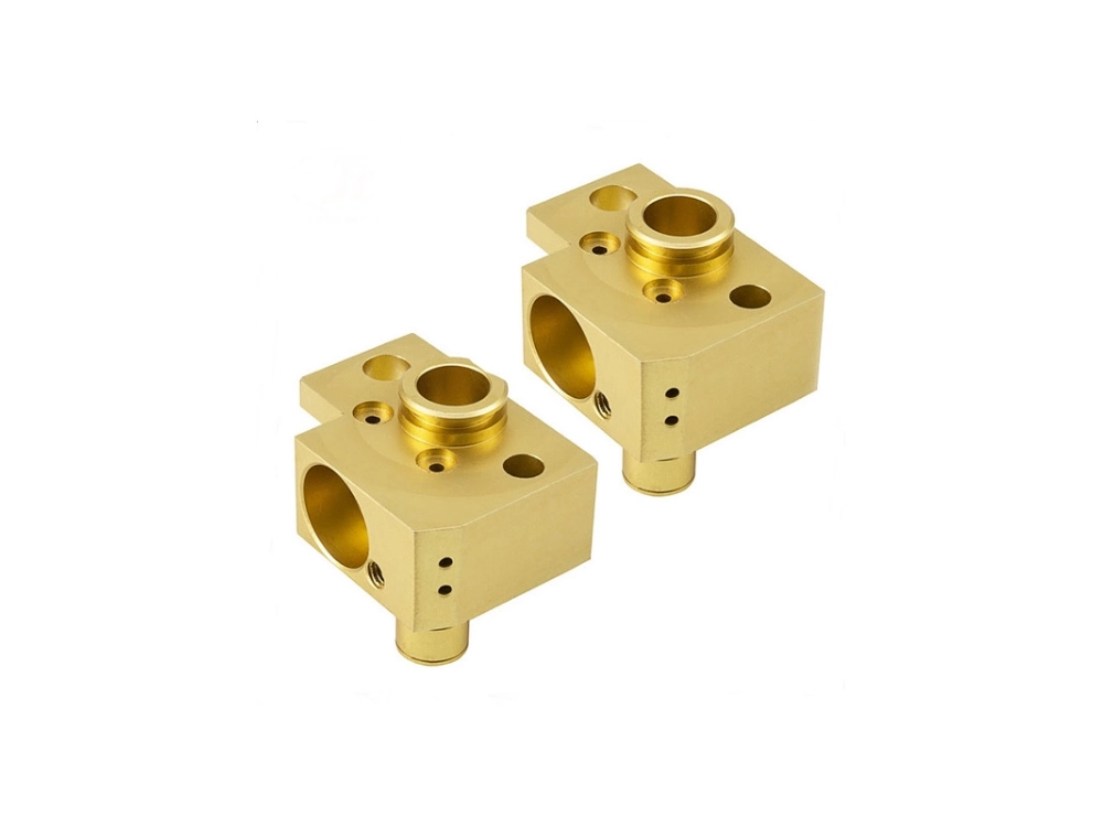

When machining complex enclosures, deep pockets, or multi-faceted housings, manufacturing engineers face a recurring trade-off: balance single-setup part precision against machine hourly rates and programming overhead. Selecting between 3-axis, 4-axis, and 5-axis CNC machining is not an arbitrary upgrade path where more axes inherently yield a superior part. Instead, it is an optimization problem governed by geometric accessibility, positional tolerance stack-up across refixturing cycles, batch
Bottom Line Up Front (BLUF):
Three-axis CNC machining operates strictly within three orthogonal Cartesian degrees of freedom ($X$, $Y$, and $Z$), maintaining a fixed cutting tool orientation perpendicular to the machine bed throughout the entire cutting path.
Kinematic Analysis and Mechanical Constraints:
In a standard vertical machining center (VMC) configuration, the cutting tool moves along three linear axes to remove material from a stationary workpiece clamped to the machine table:
$X$-Axis: Governs primary longitudinal motion (left-to-right).
$Y$-Axis: Controls transverse motion (front-to-back).
$Z$-Axis: Regulates vertical spindle height and cutting depth.
Because the cutting tool axis remains parallel to the vertical spindle centerline ($Z$-axis vector $[0, 0, 1]$), three-axis milling cannot machine undercuts, reverse draft angles, or internal compound features without manual part repositioning.
| Kinematic Attribute | Specification / Engineering Impact |
|---|---|
| Linear Axes | Three orthogonal axes ($X, Y, Z$) conforming to ISO 8## What Is the Mechanical Difference Between 3-Axis, 4-Axis, and 5-Axis CNC Machining Kinematics? |
BLUF: 3-axis CNC milling machines constrain motion strictly to three orthogonal Cartesian axes (X, Y, and Z), limiting the cutting tool to a fixed, vertical or horizontal orientation relative to the workpiece mounting face.
3-axis CNC vertical machining centers (VMCs) manipulate the cutting tool along three linear degrees of freedom:
X-Axis: Longitudinal movement (left-to-right traverse of the machine table or spindle carriage).
Y-Axis: Transverse movement (front-to-back saddle or column travel).
Z-Axis: Vertical movement (spindle extension perpendicular to the machine worktable).
In standard 3-axis CNC milling configurations, the tool axis vector remains parallel to the machine Z-axis spindle centerline throughout material removal. Because the tool orientation cannot pivot, 3-axis mills operate strictly on accessible top-down geometries in a single setup. Processing undercut profiles, angled holes, or peripheral side features requires manually unclamping the stock, flipping the component, and re-establishing the Workpiece Coordinate System (WCS) using edge finders or dial test indicators.
| Kinematic Attribute | 3-Axis CNC Machining Specification | Practical Machining Impact |
|---|---|---|
| Active Degrees of Freedom | 3 Linear (X, Y, Z) | Cutting vector remains fixed at $0^\circ$ relative to the spindle axis |
| Rotational Axes | None ($0^\circ$ table/spindle tilt) | Inability to access angled features without manual refixturing |
| Workpiece Setup Overhead | Multiple manual flips for prismatic sides | Increased cycle setup time and cumulative datum reference drift |
| Toolpath Interpolation | Linear (G01) and Circular (G02/G03) | Fast, rigid roughing with large end mills on flat, planar stock |
Consequently, 3-axis CNC milling provides maximal static machine rigidity for heavy material removal rates (MRR) on planar stock, but 3-axis kinematics restrict complex feature generation to multiple sequential workholding setups.
BLUF: 4-axis CNC machining incorporates a mechanical rotary table—typically the A-axis (rotating around the X-axis) or B-axis (rotating around the Y-axis)—to allow multi-sided peripheral machining without manual repositioning.
4-axis CNC machining kinematics combine three linear Cartesian axes (X, Y, Z) with one rotary axis. This rotary motion functions in two distinct operating modes:
Indexed 4-Axis Machining (3+1 Axis): The rotary axis functions purely as an indexer. The machine rotates the workpiece to a predetermined angular position ($\theta$), engages pneumatic or hydraulic disk brakes to clamp the rotary platter rigidly in place, and subsequently performs conventional 3-axis milling.
Continuous Simultaneous 4-Axis Machining: The rotary axis rotates continuously in dynamic synchronization with the linear X, Y, and Z axes. The Computer Numerical Control (CNC) interpolates rotational degrees per minute with linear surface feed rates. This mode generates spiral flutes, cylindrical cams, rotary extrusion dies, and continuous helical profiles.
Linear Axes:    [X: Longitudinal] <---> [Y: Transverse] <---> [Z: Tool Depth]
                                    |
Rotary Options:                    [A-Axis: Tilt Around X]
                                      - OR -
                                    [B-Axis: Tilt Around Y]
By indexing the workpiece around the centerline, 4-axis machining enables cutting operations on four contiguous radial faces in a single clamping cycle. This setup reduces operator handling and preserves geometric positioning tolerances across peripheral features.
Therefore, integrating a fourth rotational axis bridges the gap between planar prismatic milling and cylindrical machining, providing rotational indexing that eliminates secondary fixturing setups for circumferential features.
BLUF: 5-axis CNC machining integrates two rotational axes (selected from A, B, and C) alongside the three linear axes (X, Y, Z), delivering full five-sided spatial orientation and continuous cutting tool vector manipulation.
5-axis machine architectures deliver two supplementary rotational degrees of freedom through three mechanical layouts: Trunnion table-table machines (tilting/rotating worktable), Swivel head-head machines (articulated spindle head), or Head-table hybrid machines.
Industrial 5-axis CNC operations execute along two fundamentally different control methodologies:
Positional 5-Axis Machining (3+2 Positioning):
The CNC controller tilts and locks two rotary axes (such as A and C) to orient the cutting tool at a fixed compound angle toward the targeted part face.
Machining proceeds using standard 3-axis planar toolpaths.
Engineering Advantage: Machining centers run shorter, sturdier end mills at maximum spindle speeds without tool deflection or chatter, eliminating deep-reach shank vibration.
Simultaneous Continuous 5-Axis Machining:
All five axes (X, Y, Z, and two rotary axes) engage in uninterrupted, synchronized servo movement during cutting passes.
The CNC interpolates dynamic tool center point management (TCPM / RTCP) in real time to steer the cutting tool tip across complex, non-developable mathematical surfaces.
Engineering Advantage: Enables continuous multi-axis tool sweeping across turbine impellers, titanium aerospace blisks, organic prosthetic implants, and deep automotive injection mold cavities.
                [3+2 Positional Machining]                              [Simultaneous Continuous 5-Axis]
+----------------------------------+                    +------------------------------------+
| 1. Tilt axes to compound angle.  |                     | 1. Continuous dynamic interpolation |
| 2. Engage mechanical brakes.     |        VS.          |    of X, Y, Z + Rotary Axes.        |
| 3. Execute rigid 3-axis cut.     |                     | 2. Real-time RTCP/TCPM vector drift |
| 4. Maintain short tool stickout. |                     |    across freeform 3D contours.     |
+----------------------------------+                     +------------------------------------+
Understanding this kinematics distinction prevents misapplying full simultaneous 5-axis cycle times to components that require only rigid 3+2 multi-sided accessibility.
In summary, 3+2 positioning locks the tool vector to optimize rigidity and tool reach across multi-faced components, whereas continuous 5-axis kinematics dynamically drives both tool angles and linear axes simultaneously to contour complex, continuous freeform surfaces.
BLUF: Part geometry dictates machine selection when feature orientations demand cutting tools to approach stock from multiple distinct angles, or when deep cavity aspects cause excessive tool deflection and chatter.
3-axis vertical machining centers restrict tool access to planar surfaces oriented directly along the vertical spindle axis. Machine selection transitions to 4-axis or 5-axis systems when workpiece geometries exhibit specific geometric constraints:
Compound Angle Bores and Angled Bosses: Angled hole patterns and off-axis mounting bosses cannot align with a fixed vertical spindle. Machining these features on a 3-axis mill requires custom angled sine plates or dedicated angle vises, introducing setup latency.
Severe Cavity Depth-to-Diameter Ratios: Milling deep, steep-walled pockets on a 3-axis center forces operators to use extended-reach tool holders. In cutting mechanics, tool deflection increases proportionally with the cube of tool overhang length ($L^3$). Extended stickouts cause severe chatter, degraded surface roughness ($Ra > 3.2\ \mu\text{m}$), and accelerated cutting edge chipping.
Under-cut Contours and Re-entrant Features: Features shielded by workpiece overhangs remain unreachable from a single overhead vector. In contrast, 4-axis rotary positioning and 3+2 positional milling allow workpieces to tilt relative to the spindle, bringing undercut geometry into direct, rigid tool engagement.
| Geometric Feature | 3-Axis Feasibility | 4-Axis / 5-Axis Solution | Primary Engineering Benefit |
|---|---|---|---|
| Radial Cross-Holes (Cylinders) | Requires manual indexing setup | 4-Axis rotary indexing ($A$- or $B$-axis) | Zero manual re-clamping, radial alignment maintained |
| Deep Vertical Cavities ($>5:1$ Aspect) | Requires long tool stickout | 3+2 positional tilt | Shorter tool shank, higher chip load, zero chatter |
| Compound Angled Ports | Requires custom angular fixtures | 3+2 or 5-axis simultaneous positioning | Standard square fixturing, direct angular spindle approach |
| Freeform Aerodynamic Blisks | Impossible due to tool shank collision | Continuous 5-axis dynamic vector control | Uninterrupted tool engagement along compound curvatures |
Consequently, selecting 4-axis or 5-axis CNC machining solves tool clearance bottlenecks, allowing standard, short-reach carbide tooling to access complex geometries with maximum structural stiffness.
BLUF: Transitioning multi-sided parts to 4-axis or 5-axis machines eliminates secondary manual setups, directly preventing cumulative datum shift and preserving tight geometric dimensioning and tolerancing (GD&T) relationships.
In precision CNC manufacturing, positional errors accumulate every time an operator unclamps, repositions, and re-clamps a workpiece across sequential 3-axis setups. Each refixturing step introduces three independent positional error sources:
Total Positional Variance = Δclamping + Δparting_debris + ΔWCS_probing
Clamping Deformation ($\Delta_{\text{clamping}}$): Workholding vise jaws exert variable mechanical force, introducing slight elastic deformations that distort datum surfaces upon clamp release.
Interface Contamination ($\Delta_{\text{parting_debris}}$): Sub-millimeter chips or coolant residues adhering to locating parallels or soft jaws cause perpendicularity and planar tilt shifts.
Workpiece Coordinate System Probing Error ($\Delta_{\text{WCS_probing}}$): Re-establishing $X$, $Y$, and $Z$ zero datums via touch-probe or dial test indicators reintroduces runout drift.
3-Axis Multi-Setup Workflow:
[Setup 1: Top Face] ---> [Manual Unclamp & Flip] ---> [Setup 2: Side A] ---> [Manual Flip] ---> [Setup 3: Side B]
  (Datum Ref A)                                              (Tolerance Stack ±0.025mm)   (Datum Ref B)    (Tolerance Stack ±0.050mm)

5-Axis "Done-In-One" Workflow:
[Single Clamping Setup] ===> [Rotary Indexing A/C] ===> Complete Features (All Tolerances Referenced to Datum A)
Executing parts using 4-axis or 3+2/5-axis “Done-in-One” processing isolates the workpiece in a single rigid workholding cycle. Multi-axis CNC probing establishes the primary datum structure once, maintaining true position tolerances within $\pm0.010\ \text{mm}$ across intersecting bores, orthogonal faces, and peripheral bearing seats.
Therefore, multi-axis machining serves not only as a solution for complex contours, but also as a quality control mechanism for high-precision prismatic parts demanding strict spatial datums.
BLUF: Multi-axis tool manipulation maintains the cutting edge at an optimal engagement angle relative to the surface normal, avoiding zero-velocity tool-tip contact and significantly reducing surface roughness ($Ra$).
In 3-axis contouring of sculpted or sloping surfaces, machining centers typically employ ball-nose end mills. A ball-nose cutter exhibits a critical kinematic flaw: cutting velocity drops to zero directly at the center tip of the ball radius ($V_c = \pi \cdot D_{\text{eff}} \cdot N / 1000 = 0$ when effective cutter diameter $D_{\text{eff}} = 0$).
When a 3-axis mill traverses flat or low-angle slopes, this zero-velocity center contacts the workpiece, burnishing and dragging material rather than cleanly cutting it. This generates uneven galling, micro-tearing, and elevated surface roughness values ($Ra\ 1.6\text{–}3.2\ \mu\text{m}$), necessitating manual bench deburring and polishing.
Multi-axis machining counteracts this mechanism through dynamic tool lead and lean angles:
Eliminating Dead-Center Cutting: Tilting the cutting tool axis by $10^\circ\text{–}15^\circ$ via rotary axes engages the flute periphery where surface cutting speed ($V_c$) remains at peak efficiency, producing uniform shearing and superior micro-finishes ($Ra \le 0.4\ \mu\text{m}$).
Minimizing Cusp Height: Multi-axis tool tilting allows the use of large-radius barrel mills, lens cutters, or bull-nose end mills. Machinists can achieve large step-over values while maintaining minuscule scallop heights, reducing total 3D finishing cycle times by up to $60%$.
Minimizing Tool Overhang Deflection: By tilting the workpiece toward the spindle, the cutting tool approaches internal sidewalls without requiring long extensions, preserving rigidity and extending cutting tool lifespan.
In summary, multi-axis kinematic flexibility ensures consistent cutting tool contact speed and rigidity, delivering uniform surface integrity while eliminating secondary manual polishing operations.
BLUF: Choosing a machining platform purely on hourly machine rates is an accounting trap; total unit cost is governed by setup overhead, fixture complexity, cycle time, and labor intervention across the entire production run.
Machine shop rate structures reflect the capital expenditure and depreciation of CNC equipment. In standard contract manufacturing, baseline hourly operating rates vary systematically by kinematic capability:
3-Axis Vertical Machining Centers: Typically billed at $40 to $70 per hour, reflecting lower equipment acquisition costs, standard CAT40/BT30 tooling, and straightforward maintenance protocols.
4-Axis Horizontal/Vertical Centers: Billed at $60 to $100 per hour, incorporating the capital depreciation of integrated rotary platters, tombstone fixtures, and multi-pallet changers.
5-Axis Machining Centers (Trunnion/Swivel-Head): Billed at $90 to $180+ per hour, driven by premium multi-axis CNC controllers, high-resolution rotary optical encoders, dynamic crash-avoidance software licenses, and precision thermal compensation systems.
However, the machine hourly rate represents only one variable in the total manufacturing cost formula:
Unit Cost = CAM Programming Cost + Fixture Tooling Cost Batch Size (N) + ∑s=1Setups ( Setup Labor Cost N + Machining Cycle Costs + Manual Handling Labors )
When a multi-sided prismatic component runs on a 3-axis mill across 4 to 6 discrete setups, cumulative operator labor, refixturing downtime, and machine idle time often eclipse the lower nominal hourly rate. Conversely, completing that same component in a single 5-axis setup eliminates repetitive fixture changes and manual re-zeroing cycles, driving net cost per piece lower for complex batches.
| Cost & Operational Metric | 3-Axis CNC Machining | 4-Axis CNC Machining | 5-Axis CNC Machining |
|---|---|---|---|
| Nominal Machine Hourly Rate | Lowest ($40–$70/hr) | Moderate ($60–$100/hr) | Highest ($90–$180+/hr) |
| CAM Programming & Simulation Overhead | 1–3 hours (standard 2.5D/3D toolpaths) | 3–6 hours (rotary indexing & clearance checks) | 6–15+ hours (collision simulation, post-processing validation) |
| Custom Fixturing Capital Outlay | High for multi-sided parts (multiple dedicated soft jaws) | Moderate (standardized tombstones or chucks) | Low to Moderate (dovetail/zero-point self-centering vises) |
| In-Process Labor Intervention | High (manual operator flips between setups) | Low (batch indexing on tombstones) | Minimal (“Done-In-One” single clamping sequence) |
Consequently, 3-axis milling delivers superior cost-efficiency for flat, single-face plates, whereas 4-axis and 5-axis platforms achieve lower total unit costs whenever multi-setup labor hours exceed machine amortization differences.
BLUF: The economic cross-over between 3-axis, 4-axis, and 5-axis processes shifts depending on production batch scale, driven by how upfront programming and fixturing amortize across total delivered parts.
Evaluating production batches requires dividing manufacturing orders into distinct volume tiers:
Production Scale Spectrum:
[Rapid Prototyping: 1–10 pcs]  ====>  [Low-to-Mid Volume: 50–500 pcs]  ====>  [High-Volume Production: >1,000 pcs]
           |                                         |                                         |
* 5-Axis Positional shines:               * 4-Axis Tombstone / Horizontal          * Dedicated multi-station 3-axis
  No hard fixturing needed;                 shines: High-density batching,           lines or high-volume 4/5-axis cells
  dovetail clamps cut prep days.            reduced cycle time via batch indexing.   with automated robotic loading.
Rapid Prototyping & Low-Volume Production (1 to 50 pieces):
Developing bespoke soft jaws and manual flip fixtures for 3-axis multi-sided milling introduces long lead times and high non-recurring engineering (NRE) fixture expenses.
Utilizing 5-axis positional (3+2) machining allows machinists to secure raw billet stock in a standard dovetail vise or zero-point self-centering clamp and machine five accessible faces in a single operation.
Despite higher initial CAM programming and machine hourly rates, the elimination of custom fixture fabrication makes 5-axis machining the fastest and most economical route for quick-turn prototypes.
Medium-Volume Batch Production (50 to 1,000 pieces):
In this volume window, 4-axis Horizontal Machining Centers (HMCs) with rotary tombstones become exceptionally cost-effective.
Operators mount dozens of parts around a 4-sided tombstone on a dual-pallet changer. The machine processes components around the $B$-axis rotary indexing positions while the operator safely unloads finished parts and loads raw blanks on the external station.
This architecture achieves near-100% spindle duty cycles and spreads NRE setup expenses over hundreds of units, outcompeting standalone 3-axis and high-hourly 5-axis setups.
High-Volume Production (>1,000 pieces):
When part geometry is fundamentally planar or simple, amortized fixture tooling costs approach zero per unit.
High-speed, high-rigidity 3-axis mills operating in tandem or multi-station configurations often yield the lowest unit cost, as parts avoid paying the overhead of unused rotary axes and premium machine depreciation.
Therefore, prototype runs favor 5-axis flexibility to bypass custom fixturing costs, mid-volume batches leverage 4-axis tombstone capacity to maximize throughput, and high-volume prismatic runs rely on dedicated 3-axis efficiency.
BLUF: Evaluating machining economics requires pricing hidden operational risks, including programming and simulation overhead, operator loading mistakes during intermediate setups, and cumulative scrap costs.
Beyond direct machine runtime, three hidden operational factors substantially impact bottom-line project profitability:
CAM Programming and Verification Lead Time:
3-axis CAM toolpaths require standard post-processors and minimal clearance checking.
In contrast, continuous 5-axis milling demands rigorous computer simulation (e.g., Vericut or CAM-integrated collision detection) to prevent dynamic interference between the articulated spindle head, workholding jaws, and tilting table.
For low-complexity geometries, investing 8 hours of senior CAM programming and simulation validation on a 5-axis part that could be machined on a 3-axis mill with 45 minutes of programming represents an operational loss.
Human Operator Dependency and Setup Variability:
Every manual part repositioning on a 3-axis table introduces operator-dependent error risks. An operator overtightening a vise screw, failing to sweep out fine aluminum chips from the locating pin, or misaligning an edge-finder zero reference converts expensive semi-finished components into immediate scrap.
In critical industries like aerospace and medical device manufacturing, scrap on the final operation of a multi-setup workflow destroys accumulated raw material and upstream machining value.
First-Part Yield and Process Reliability:
With 5-axis “Done-In-One” manufacturing, workpieces maintain their verified datum structure throughout the machining cycle.
Implementing in-process touch probes on 5-axis centers enables automated Workpiece Coordinate System calibration, cutting tool wear verification, and feature measurement before part ejection, elevating first-part yield close to 100%.
In summary, 5-axis machining demands higher front-end programming investments and CAM validation, but it insulates high-value projects against downstream operator clamping errors and scrap losses common in multi-setup 3-axis workflows.
BLUF: Platform selection requires evaluating part geometry, feature accessibility, positional tolerance schemes, and production run sizes against a structured engineering matrix rather than relying on equipment availability.
To select the correct machining process, design and manufacturing engineers must benchmark component drawings against five core manufacturing constraints:
Feature Distribution and Spatial Symmetry: Planar, single-face features align with 3-axis capabilities. Radially distributed holes, slots, or peripheral contours along a cylindrical or prismatic axis demand 4-axis indexing. Compound angled bores, orthogonal multi-sided features, and continuous 3D organic surfaces require 3+2 positional or continuous 5-axis architectures.
True Position and Datum Alignment (GD&T): When geometric tolerances require tight coaxiality, perpendicularity, or true position within $\le 0.025\ \text{mm}$ across features on multiple faces, multi-axis single-setup processing eliminates cumulative refixturing stack-up error.
Cavity Depth and Tool Clearance Ratios: Aspect ratios exceeding $4:1$ on vertical cavity walls generate tool deflection on 3-axis mills, whereas 5-axis positional tilting maintains short tool overhang ratios ($\le 3:1$).
Tooling and Fixture Capitalization (NRE): Low-volume runs cannot justify multi-station soft-jaw fabrication; single-clamping dovetail workholding on 5-axis platforms minimizes fixturing expense.
CAM Programming and Verification Lead Time: When production runs require quick turnaround and geometry does not mandate tool-vector tilting, the lower CAM programming overhead of 3-axis toolpaths delivers faster first-article production.
| Evaluation Parameter | 3-Axis CNC Machining | 4-Axis CNC Machining | 5-Axis CNC Machining (3+2 / Continuous) |
|---|---|---|---|
| Dominant Part Geometry | Flat plates, 2.5D prismatic pockets, top-down mounting faces | Shafts, fluted cylinders, prismatic parts with 4 radial faces | Impellers, turbine blades, complex manifolds, 5-sided housings |
| Typical True Position Capability | $\pm0.050\ \text{mm}$ across multi-setup features | $\pm0.020\ \text{mm}$ across radial indexed features | $\le \pm0.010\ \text{mm}$ in single-setup “Done-In-One” |
| Max Cavity Aspect Ratio ($L/D$) | Up to $3:1$ before severe chatter occurs | Up to $4:1$ using rotary orientation | $>5:1$ achieved via compound angular approach |
| Workholding Strategy | Standard modular vises, custom soft jaws, step clamps | Rotary chucks, center tailstocks, 4-sided tombstones | Zero-point bases, dovetail clamps, self-centering vises |
| Optimal Batch Window | High-volume flat components or simple prototypes | Medium-to-high volume batch production on tombstones | Complex low-volume prototypes or tight-tolerance multi-face runs |
Applying this multi-variable matrix prevents both the under-machining of complex geometric housings and the unnecessary capital expense of running standard 2.5D parts on continuous 5-axis equipment.
BLUF: Industrial application examples illustrate how matching part features to kinematic capabilities lowers total unit production costs and prevents out-of-spec scrap.
Real-world contract manufacturing projects reveal the operational mechanisms behind platform selection:
Case 1: Aerospace Hydraulic Manifold Block (6061-T6 Aluminum)
Component Features: 18 intersecting fluid passages, 6 cross-angled valve ports, and strict bore perpendicularity ($\le 0.015\ \text{mm}$) across five exterior faces.
Process Comparison: On a 3-axis vertical machining center, this manifold required five individual workholding setups using custom soft jaws. Cumulative datum shift caused a $14%$ scrap rate on internal valve port intersections due to slight angular misalignment.
Multi-Axis Solution: Transitioning the component to a 5-axis trunnion machining center using a dovetail preparation clamp allowed complete five-sided feature generation in a single clamping cycle. Total setup and machining time dropped from 115 minutes to 42 minutes per block, and part-to-part positional variation remained within $\pm0.008\ \text{mm}$.
Case 2: Industrial Rotary Drive Cam (4140 Alloy Steel)
Component Features: Cylindrical base shaft with continuous, variable-pitch helical cam tracks cut around the outer diameter, paired with perpendicular keyways.
Process Comparison: A 3-axis mill could not cut the variable-pitch profile without continuous part rotation. Attempting manual indexing on an auxiliary rotary table yielded uneven cutter marks and facet steps along the groove.
Multi-Axis Solution: Utilizing a continuous 4-axis horizontal mill with an integrated $A$-axis rotary table enabled simultaneous rotation while the $X, Y,$ and $Z$ axes interpolated the cutter path. Surface finish met the drawing requirement ($Ra \le 0.8\ \mu\text{m}$) directly from the cutter path, removing manual bench finishing.
Case 3: Electronic Enclosure Heatsink Baseplate (AL5052)
Component Features: Large rectangular footprint ($350\ \text{mm} \times 250\ \text{mm}$) with 48 high-density cooling fins and four corner clearance mounting holes on the top face only.
Process Comparison: Processing this part on a 5-axis center incurred unnecessary machine hourly rates without providing geometric benefit, as the cutting tool never required angular tilting.
Multi-Axis Solution: Allocating the baseplate to a high-speed, high-rigidity 3-axis vertical machining center with dual pneumatic vises enabled aggressive roughing feed rates ($>3,500\ \text{mm/min}$) using an indexable face mill. This approach achieved the lowest cost per unit at minimal programming and tooling overhead.
These industrial examples confirm that machine selection is governed by geometric accessibility and tolerance requirements, not by maximizing kinematic complexity for its own sake.
What Technical Information Must Engineers Include in a Precision Machining RFQ?
BLUF: Providing comprehensive technical manufacturing requirements in a Request for Quotation (RFQ) enables machine shops to calculate precise cycle times, select the most cost-effective machine platform, and avoid pricing contingencies.
When sourcing precision CNC machined components, engineering teams must supply critical process definitions beyond basic 3D CAD models (such as STEP or IGES formats):
Fully Dimensioned 2D Drawings with GD&T Schemes:
Supply native vector 2D drawings (PDF format) explicitly defining primary, secondary, and tertiary datum reference frames.
State acceptable geometric tolerances (true position, parallelism, concentricity, and profile of a surface) to indicate whether a “Done-In-One” multi-axis setup is mathematically necessary to avoid datum stack-up error.
Surface Roughness and Visual Finish Specifications:
Explicitly define required surface roughness values ($Ra$ or $Rz$) for functional mating surfaces versus non-critical clearance pockets.
Indicate whether parts require bead blasting, sulfuric acid anodizing (Type II/III), chemical conversion coating, or passivation, as post-finishing layer thickness affects pre-machining dimensional## How Should Sourcing Engineers Formulate an Actionable Machine Selection Decision Framework?
What Engineering Checklists and Rules of Thumb Determine Axis Selection?
BLUF: Axis selection requires evaluating geometric accessibility, datum reference schemes, production batch sizes, and raw material removal mechanics against a defined technical threshold.
Sourcing teams and design engineers avoid costly misallocations by vetting CAD models against practical machining criteria before issuing a Request for Quotation (RFQ). The following checklist outlines the
BLUF: Axis selection requires evaluating geometric accessibility, datum reference schemes, production batch sizes, and raw material removal mechanics against structured technical thresholds rather than nominal machine availability.
Sourcing teams and mechanical design engineers eliminate costly misallocations by vetting CAD models against practical machining criteria before releasing purchase orders:
The Multi-Face Rule: If a prismatic component requires operations on three or more orthogonal or angled faces, calculate total setup handling time. If cumulative manual setup time exceeds projected cutting cycle time on a 3-axis machine, route the part directly to a 4-axis tombstone or 5-axis positional center.
The True-Position Threshold: When engineering drawings dictate true position tolerances tighter than $\pm0.025\ \text{mm}$ across features located on opposing or perpendicular surfaces, select single-clamping 5-axis CNC machining (or 4-axis continuous rotary indexing). Multiple manual 3-axis refixturing steps carry inherent datum drift risks exceeding this threshold.
The Tool-Aspect Ratio Boundary: For cavity depths exceeding four times the cutting tool diameter ($L/D > 4:1$), prioritize 3+2 positional tilting. Tilting the part allows standard-length carbide end mills to reach deep internal corners, preventing cutting edge chatter, tool deflection, and micro-cracking.
The True Organic Contour Mandate: Reserve simultaneous continuous 5-axis machining strictly for non-developable 3D compound surfaces—such as aerodynamic impellers, flow manifolds, turbine blades, and orthopedic implants—where continuous cutting tool vector manipulation is mathematically required to prevent gouging.
| Part Feature & Production Requirement | Primary Machine Candidate | Decision Justification |
|---|---|---|
| Flat plates, shallow brackets, top-access bosses | 3-Axis CNC Mill | Maximizes static structural rigidity, reduces machine hourly rate, and requires minimal CAM setup. |
| Cylindrical shafts with radial bores or splines | 4-Axis Mill-Turn / Rotary VMC | Combines linear traverse with radial indexing in a single clamping cycle; eliminates off-axis sine fixturing. |
| Medium-to-high volume multi-sided housings | 4-Axis Horizontal Machining Center (HMC) | Leverages multi-sided tombstones with pallet changers to maintain high spindle duty cycles. |
| 5-sided prismatic enclosures with tight spatial datums | 3+2 Positional 5-Axis Center | Reaches five accessible faces via rigid rotational locking; cuts tooling overhang and avoids custom soft jaws. |
| Continuous complex airfoils, dynamic flow impellers | Simultaneous Continuous 5-Axis Center | Drives 5-axis dynamic tool center point management (RTCP) to maintain cutting edge normal to compound surfaces. |
Applying this structured checklist ensures machine platform allocation matches physical feature demands while preventing the operational waste of running basic 2.5D parts on premium multi-axis systems.
BLUF: Providing comprehensive geometric, tolerance, and finishing definitions in a Request for Quotation (RFQ) enables manufacturing partners to calculate precise cycle times, select the most cost-effective machine platform, and eliminate risk-pricing markups.
When sourcing precision custom parts, engineering teams must supply critical process definitions beyond neutral 3D CAD files (STEP/IGES):
Fully Dimensioned 2D Drawings with GD&T Callouts:
Supply native vector 2D drawings (PDF format) explicitly defining primary, secondary, and tertiary datum reference frames ($A$, $B$, and $C$).
Clearly define geometric tolerances (true position, parallelism, concentricity, and profile of a surface). This clarifies whether a single-setup multi-axis workflow is required to eliminate cumulative fixture stack-up error.
Surface Roughness and Visual Finish Classifications:
Explicitly define required surface roughness values ($Ra$ or $Rz$) for critical mating faces versus non-critical clearance areas.
State post-processing requirements—such as bead blasting, Type II/III sulfuric anodizing, electroless nickel plating, or passivation—because surface layer accumulation impacts pre-machining dimensional offsets.
Material Grade, Temper, and Traceability Standards:
Specify exact alloy designations, tempers, and treatment conditions (e.g., 6061-T651, 17-4 PH H1150, Ti-6Al-4V Grade 5).
Note raw material certification mandates, such as mill test reports (MTR), ultrasonic inspection (UT) per AMS specifications, or RoHS/REACH compliance.
Production Batch Phasing and Delivery Schedules:
State prototype sample quantities, initial production run volumes, and anticipated annual usage (EAU).
Volume definitions guide the manufacturing engineer’s tooling strategy—determining whether to build modular 3-axis soft jaws, install a 4-axis multi-part tombstone fixture, or program a 5-axis zero-point workholding receiver.
+---------------------------------------------------------------------------------+
| [X] 3D CAD Geometry: STEP / Parasolid format for automated CAM toolpathing      |
| [X] 2D Engineering Drawings: PDF format showing GD&T datums, threads & fits     |
| [X] Material & Heat Treatment: Specific alloy, hardness/temper, MTR requirement |
| [X] Critical Tolerances: Explicit true position callouts on cross-face features |
| [X] Surface Roughness & Finishes: Defined Ra values and chemical coating specs  |
| [X] Batch Scale: First-article prototype counts, production lots, and EAU       |
+---------------------------------------------------------------------------------+
Supplying an unambiguous RFQ package enables CNC machine suppliers to accurately match part geometries with the most cost-effective machine kinematics, preventing quoting delays and costly design-for-manufacturing (DFM) revisions.
BLUF: Leveraging a balanced machine inventory across high-speed 3-axis mills, rotary 4-axis horizontal centers, and advanced 5-axis simultaneous machines allows manufacturing partners to route components to the lowest-cost kinematic platform without compromising quality.
Precision contract manufacturer ChiHeng applies a data-driven routing strategy to resolve the trade-off between machine hourly rates and refixturing labor:
Right-Machine Allocation: Rather than routing all incoming orders to high-rate 5-axis machines, ChiHeng evaluates component topology during upfront Engineering DFM reviews. Planar brackets and structural plates remain on high-speed 3-axis centers to minimize run-hour costs, while complex housings and angled manifolds are routed directly to 3+2 or 5-axis continuous cells.
Standardized Quick-Change Workholding: Utilizing modular zero-point clamping grids and standard dovetail fixtures across multi-axis machine beds reduces machine setup times from several hours to under 15 minutes. This fixturing standardization makes low-volume 5-axis prototyping commercially competitive with conventional 3-axis fabrication.
Rigorous Quality Assurance and Metrology: Multi-axis parts undergo comprehensive First Article Inspection (FAI) using automated Coordinate Measuring Machines (CMM), optical profilometers for surface micro-roughness ($Ra$), and material verification via XRF alloy analyzers. In-process probing routines verify datum integrity inside the machine envelope before raw stock unclamp, guaranteeing conformance with customer GD&T schemes.
BLUF: Axis selection requires evaluating geometric accessibility, datum reference schemes, production batch sizes, and raw material removal mechanics against structured technical thresholds rather than nominal machine availability.
Sourcing teams and mechanical design engineers eliminate costly misallocations by vetting CAD models against practical machining criteria before releasing purchase orders:
The Multi-Face Rule: If a prismatic component requires operations on three or more orthogonal or angled faces, calculate total setup handling time. If cumulative manual setup time exceeds projected cutting cycle time on a 3-axis machine, route the part directly to a 4-axis tombstone or 5-axis positional center.
The True-Position Threshold: When engineering drawings dictate true position tolerances tighter than $\pm0.025\ \text{mm}$ across features located on opposing or perpendicular surfaces, select single-clamping 5-axis CNC machining (or 4-axis continuous rotary indexing). Multiple manual 3-axis refixturing steps carry inherent datum drift risks exceeding this threshold.
The Tool-Aspect Ratio Boundary: For cavity depths exceeding four times the cutting tool diameter ($L/D > 4:1$), prioritize 3+2 positional tilting. Tilting the part allows standard-length carbide end mills to reach deep internal corners, preventing cutting edge chatter, tool deflection, and micro-cracking.
The True Organic Contour Mandate: Reserve simultaneous continuous 5-axis machining strictly for non-developable 3D compound surfaces—such as aerodynamic impellers, flow manifolds, turbine blades, and orthopedic implants—where continuous cutting tool vector manipulation is mathematically required to prevent gouging.
| Part Feature & Production Requirement | Primary Machine Candidate | Decision Justification |
|---|---|---|
| Flat plates, shallow brackets, top-access bosses | 3-Axis CNC Mill | Maximizes static structural rigidity, reduces machine hourly rate, and requires minimal CAM setup. |
| Cylindrical shafts with radial bores or splines | 4-Axis Mill-Turn / Rotary VMC | Combines linear traverse with radial indexing in a single clamping cycle; eliminates off-axis sine fixturing. |
| Medium-to-high volume multi-sided housings | 4-Axis Horizontal Machining Center (HMC) | Leverages multi-sided tombstones with pallet changers to maintain high spindle duty cycles. |
| 5-sided prismatic enclosures with tight spatial datums | 3+2 Positional 5-Axis Center | Reaches five accessible faces via rigid rotational locking; cuts tooling overhang and avoids custom soft jaws. |
| Continuous complex airfoils, dynamic flow impellers | Simultaneous Continuous 5-Axis Center | Drives 5-axis dynamic tool center point management (RTCP) to maintain cutting edge normal to compound surfaces. |
Applying this structured checklist ensures machine platform allocation matches physical feature demands while preventing the operational waste of running basic 2.5D parts on premium multi-axis systems.
BLUF: Providing comprehensive geometric, tolerance, and finishing definitions in a Request for Quotation (RFQ) enables manufacturing partners to calculate precise cycle times, select the most cost-effective machine platform, and eliminate risk-pricing markups.
When sourcing precision custom parts, engineering teams must supply critical process definitions beyond neutral 3D CAD files (STEP/IGES):
Fully Dimensioned 2D Drawings with GD&T Callouts:
Supply native vector 2D drawings (PDF format) explicitly defining primary, secondary, and tertiary datum reference frames ($A$, $B$, and $C$).
Clearly define geometric tolerances (true position, parallelism, concentricity, and profile of a surface). This clarifies whether a single-setup multi-axis workflow is required to eliminate cumulative fixture stack-up error.
Surface Roughness and Visual Finish Classifications:
Explicitly define required surface roughness values ($Ra$ or $Rz$) for critical mating faces versus non-critical clearance areas.
State post-processing requirements—such as bead blasting, Type II/III sulfuric anodizing, electroless nickel plating, or passivation—because surface layer accumulation impacts pre-machining dimensional offsets.
Material Grade, Temper, and Traceability Standards:
Specify exact alloy designations, tempers, and treatment conditions (e.g., 6061-T651, 17-4 PH H1150, Ti-6Al-4V Grade 5).
Note raw material certification mandates, such as mill test reports (MTR), ultrasonic inspection (UT) per AMS specifications, or RoHS/REACH compliance.
Production Batch Phasing and Delivery Schedules:
State prototype sample quantities, initial production run volumes, and anticipated annual usage (EAU).
Volume definitions guide the manufacturing engineer’s tooling strategy—determining whether to build modular 3-axis soft jaws, install a 4-axis multi-part tombstone fixture, or program a 5-axis zero-point workholding receiver
+---------------------------------------------------------------------------------+
| [X] 3D CAD Geometry: STEP / Parasolid format for automated CAM toolpathing      |
| [X] 2D Engineering Drawings: PDF format showing GD&T datums, threads & fits     |
| [X] Material & Heat Treatment: Specific alloy, hardness/temper, MTR requirement |
| [X] Critical Tolerances: Explicit true position callouts on cross-face features |
| [X] Surface Roughness & Finishes: Defined Ra values and chemical coating specs  |
| [X] Batch Scale: First-article prototype counts, production lots, and EAU       |
+---------------------------------------------------------------------------------+
Supplying an unambiguous RFQ package enables CNC machine suppliers to accurately match part geometries with the most cost-effective machine kinematics, preventing quoting delays and costly design-for-manufacturing (DFM) revisions.
How Does ChiHeng Leverage Multi-Axis Capabilities to Optimize Machining Solutions?
BLUF: Leveraging a balanced machine inventory across high-speed 3-axis mills, rotary 4-axis horizontal centers, and advanced 5-axis simultaneous machines allows manufacturing partners to route components to the lowest-cost kinematic platform without compromising quality.
Precision contract manufacturer ChiHeng applies a data-driven routing strategy to resolve the trade-off between machine hourly rates and refixturing labor:
Right-Machine Allocation: Rather than routing all incoming orders to high-rate 5-axis machines, ChiHeng evaluates component topology during upfront Engineering DFM reviews. Planar brackets and structural plates remain on high-speed 3-axis centers to minimize run-hour costs, while complex housings and angled manifolds are routed directly to 3+2 or 5-axis continuous cells.
Standardized Quick-Change Workholding: Utilizing modular zero-point clamping grids and standard dovetail fixtures across multi-axis machine beds reduces machine setup times from several hours to under 15 minutes. This fixturing standardization makes low-volume 5-axis prototyping commercially competitive with conventional 3-axis fabrication.
Rigorous Quality Assurance and Metrology: Multi-axis parts undergo comprehensive First Article Inspection (FAI) using automated Coordinate Measuring Machines (CMM), optical profilometers for surface micro-roughness ($Ra$), and material verification via XRF alloy analyzers. In-process probing routines verify datum integrity inside the machine envelope before raw stock unclamp, guaranteeing conformance with customer GD&T schemes.
By aligning CAD geometry directly with optimized kinematics, tooling overhangs, and automated verification protocols, ChiHeng delivers high-tolerance components on schedule while minimizing total part unit manufacturing costs.
3-axis CNC machines move along orthogonal Cartesian axes ($X, Y, Z$) at a fixed tool angle, 4-axis adds one rotary degree of freedom ($A$ or $B$) for circumferential operations, and 5-axis integrates two rotary axes to position or dynamically sweep the cutting tool across complex compound surfaces.
No; while 5-axis machine hourly rates are $50%\text{--}150%$ higher, single-setup "Done-In-One" 5-axis execution is often cheaper for multi-sided parts because it eliminates multiple custom fixtures, manual re-clamping labor, and cumulative scrap risks.
Positional 3+2 machining locks two rotary axes at fixed compound angles to perform rigid 3-axis milling with shorter tools, whereas continuous 5-axis dynamically coordinates all five axes simultaneously to machine continuous non-developable contours like impellers.
Single-setup 5-axis machining maintains true position tolerances within $\le \pm0.010\ \text{mm}$ across multi-faceted features, whereas multi-setup 3-axis processes typically stack positional tolerance drift up to $\pm0.050\ \text{mm}$ due to manual refixturing and datum realignment errors.
Choose 4-axis machining for cylindrical shafts requiring radial milling, continuous helical cams, or medium-to-high batch production using multi-sided tombstones on horizontal machining centers (HMCs) where secondary compound tilt angles are not required.
Yes; tilting the cutter axis by $10^\circ\text{--}15^\circ$ avoids the zero-velocity dead center of ball-nose end mills, eliminating material dragging and enabling surface finishes of $Ra \le 0.4\ \mu\text{m}$ directly off the machine without manual polishing.
Stop thinking more, fill out the blank below, and send us an inquiry, and you will have a professional team of board game custom products contact you to answer any questions and provide pricing.
You can send us any questions to get any information you would like to know, and we will respond to you in extremely short time.