
Flexible couplings are mechanical connectors that join two rotating shafts while tolerating misalignment, absorbing shock/vibration, and transmitting torque with controlled flexibility. In this guide, you’ll learn the 7 most common types of flexible couplings (jaw, disc, gear, grid, elastomeric, Oldham, beam), their pros/cons, a high-signal comparison table, a 5-step selection workflow, plus how Chiheng Hardware CNC-machines custom hubs/spiders/flanges/disc packs for OEM and replacement needs. Wrong coupling selection is a top cause of bearing failure, seal leakage, shaft fatigue, overheating, and unexpected downtime—so use this page as a practical selection reference.
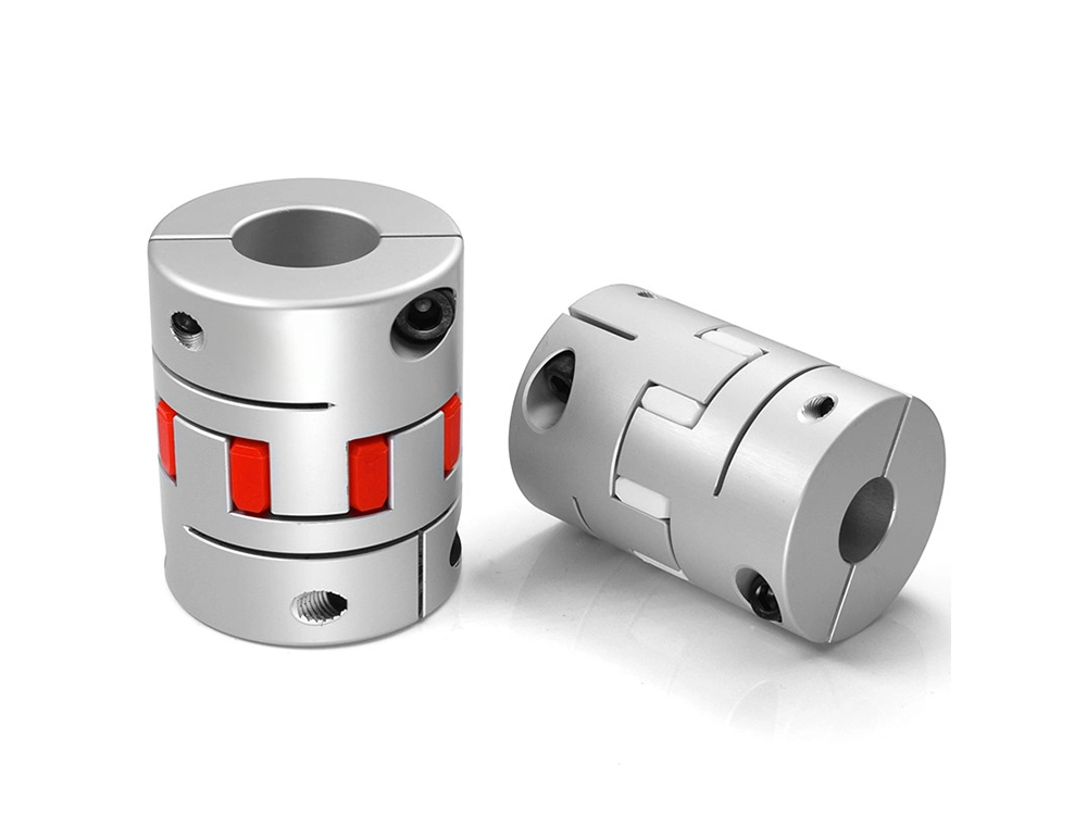
Flexible couplings connect two shafts while accommodating misalignment, absorbing shock, and transmitting torque without requiring perfectly rigid shaft alignment.
Rigid coupling: locks two shafts together like one solid shaft; virtually no flexibility.
Flexible coupling: allows controlled movement to protect bearings, seals, and shafts from misalignment and vibration loads.
Read entire types of mechanical couplings page here.
Rigid vs Flexible Coupling Comparison
| Feature | Rigid Coupling | Flexible Coupling |
|---|---|---|
| Alignment requirement | Very high | Medium / Low |
| Vibration damping | None | Yes |
| Maintenance cost | Low | Medium |
| Typical applications | Precision shafting | Motors / pumps / compressors |
Misalignment compensation (angular / parallel / axial, depending on type)
Vibration damping (reduces resonance, noise, fatigue)
Overload protection (many designs reduce shock peaks to protect equipment)
Flexible couplings mainly deal with three misalignment types:
| Misalignment Type | What it means | Typical cause |
|---|---|---|
| Angular | Shafts meet at an angle (not colinear) | imperfect mounting, soft foot |
| Parallel (Offset) | Shafts are parallel but displaced | base shift, machining tolerance |
| Axial (End float) | Shaft distance changes along axis | thermal growth, thrust movement |
The main types of flexible shaft couplings include jaw, disc, gear, grid, elastomeric (rubber), Oldham, and beam couplings—each suited to different torque, speed, damping, and misalignment requirements.
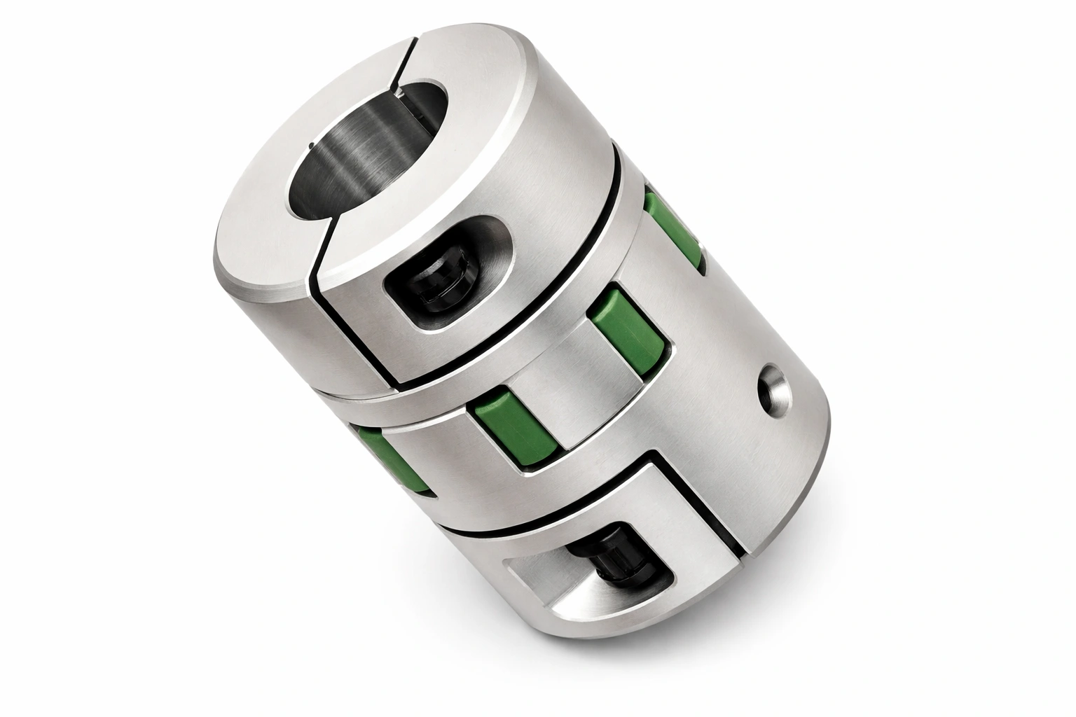
A jaw (spider) coupling uses two jaw hubs and an elastomer “spider” insert to transmit torque with high damping and moderate misalignment tolerance.

How it works (conceptual): Two metal hubs with jaws compress an elastomer spider; torque transfers through elastomer deformation (which also damps vibration).
Pros
High shock absorption and vibration damping
Handles angular + parallel misalignment (within rating)
Simple, cost-effective, easy insert replacement
Cons
Insert is a wear item (heat, oil, ozone affect life)
Not ideal for ultra-high precision torsional rigidity
Torque density lower than gear couplings at same size
Typical applications
Servo motors, general motor drives
Pumps, light-to-medium compressors
Chiheng CNC angle: custom aluminum/steel hubs + polyurethane spiders (hardness tuned to damping vs stiffness)
A disc coupling transmits torque through stainless disc packs for high torsional stiffness and high-speed precision, with limited damping.
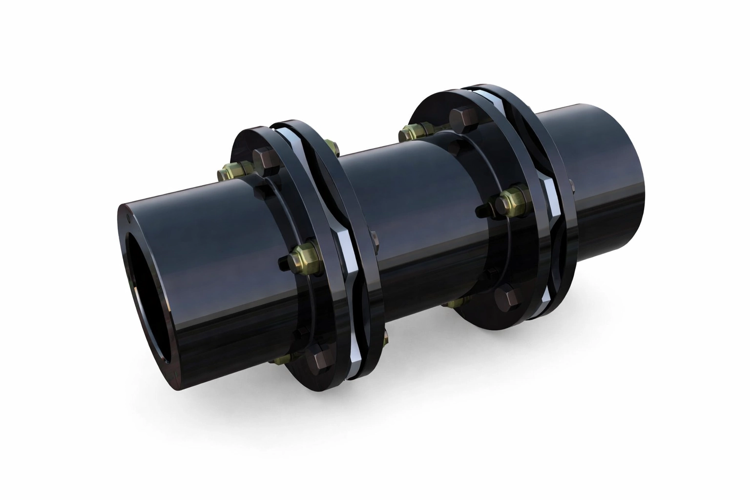
Structure: Laminated disc packs bolted between hubs; flex comes from disc bending.
Pros
High torsional stiffness (control accuracy)
Great for high speed and dynamic balance
No elastomer wear in clean setups
Cons
Low damping (can pass vibration)
Often limited axial float—verify spec for thermal growth
Bolted joints need correct torque/inspection
Typical applications
High-speed turbines
Precision machinery, test rigs
Note: Many disc designs are angular-focused and don’t like large axial movement.
A gear coupling uses internal/external gear teeth (usually lubricated) to deliver very high torque capacity with multi-axis misalignment capability.

Principle: Crowned gear teeth and lubrication film allow misalignment while transmitting heavy torque.
Pros
High–very high torque density
Suitable for heavy duty cycles
Can accommodate multiple misalignment types (when maintained)
Cons
Needs lubrication + sealing (maintenance requirement)
Misalignment + poor lubrication accelerates tooth wear
Heavier/more complex than jaw/Oldham
Typical applications
Steel mills, heavy industry, crushers, mixers
High torque flexible shaft coupling use cases
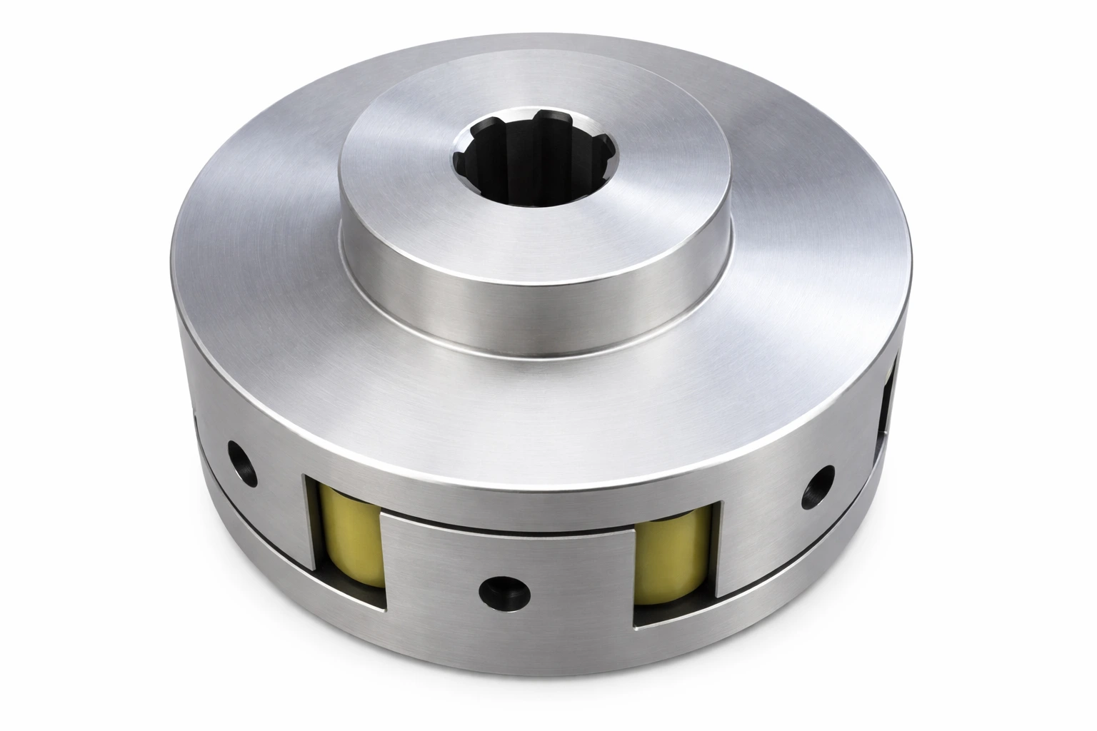
A grid coupling uses a spring-steel grid element to transmit torque while providing excellent shock-load damping for industrial drives.

Structure: Serpentine grid sits in hub grooves and flexes under load changes.
Pros
Excellent for shock loads and vibration damping
Medium–high torque capability
Rugged for plant environments
Cons
Often uses lubrication; periodic inspection helps reliability
Grid element can wear over time
Not as torsionally stiff as disc couplings
Typical applications
Fans, conveyors, compressors
Material handling systems with starts/stops
An elastomeric coupling uses rubber/urethane elements (tire/sleeve styles) to deliver very high damping and broad misalignment tolerance for general drives.

Common element types
Tire type: rubber tire bolted between flanges
Sleeve type: elastomer sleeve connects hubs
Pros
Very high damping (noise/vibration control)
Handles angular/parallel/axial misalignment (within rating)
Helps protect bearings/seals from shock and resonance
Cons
Elastomer ages (temperature, oil/chemicals, ozone)
Lower torque density than gear/grid
Element replacement is normal maintenance
Typical applications
Flexible couplings for motors
General industrial drives, conveyors, fans
An Oldham coupling is a three-piece coupling designed for high parallel offset misalignment using a floating center disc.

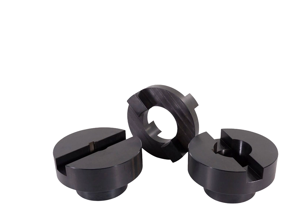
Structure: Two slotted hubs + a sliding floating disc.
Pros
Excellent parallel offset capability
Can provide electrical isolation (disc material dependent)
Compact and cost-effective for light duty
Cons
Low torque capacity
Center disc wears (sliding friction)
Not ideal for high shock loads
Typical applications
Encoders
Light-duty motion control
A beam (helical) coupling is a single-piece slotted metal coupling that provides zero-backlash potential for small motion systems with low damping.

Structure: One-piece aluminum/stainless with helical cuts.
Pros
Compact, zero-backlash options
Good for precision positioning
No elastomer insert to replace
Cons
Low damping
Low torque compared with gear/grid
Excess misalignment can cause fatigue cracking
Typical applications
Stepper motors
CNC axis drives, small robots
| Type | Torque Range | Misalignment Tolerance | Damping | Best For |
|---|---|---|---|---|
| Jaw | Low–Medium | Angular + Parallel | High | Servo, pumps |
| Disc | Medium–High | Angular only | Low | High-speed precision |
| Gear | High–Very High | All types | Medium | Heavy industry |
| Grid | Medium–High | All types | High | Shock loads |
| Elastomeric | Low–Medium | All types | Very High | Motors, conveyors |
| Oldham | Low | Parallel offset | Medium | Encoders |
| Beam | Low | All types | Low | CNC, steppers |
Extra decision fields:
| If you need… | Usually start with… |
|---|---|
| Highest torque density | Gear |
| Shock load + damping | Grid / Elastomeric / Jaw |
| High speed + precision stiffness | Disc / Beam |
| Mainly parallel offset | Oldham |
| Low maintenance (no grease) | Jaw / Disc / Beam / many Elastomeric (verify) |
Flexible couplings are used wherever two shafts must transmit torque while handling misalignment or vibration—common in motors, pumps, compressors, conveyors, and CNC machinery.
Motor-to-pump connections (flexible couplings for motors): reduce vibration, protect seals/bearings
CNC / servo drive systems: accuracy + tolerance (jaw, beam, disc)
Compressors & blowers: shock + thermal growth (grid, elastomeric, gear)
Conveyors & material handling: frequent starts/stops (grid, elastomeric, jaw)
Marine & wind energy: misalignment + load variation (gear, grid, elastomeric)
Industry reference terms like Lovejoy or “Sure-Flex” are often used to describe popular coupling families and formats in real plant procurement and maintenance conversations.
Rigid couplings make two shafts behave as one unit; flexible couplings allow controlled movement to protect bearings, seals, and connected equipment.
Practical differences
Rigid: best when alignment is extremely accurate and stable; transfers vibration and misalignment forces into bearings.
Flexible: tolerates real-world misalignment; reduces bearing/seal loads; often reduces noise and fatigue failures.
Decision tree
If you expect misalignment/thermal movement → choose flexible.
If your system has shock loads or vibration → choose flexible (jaw/elastomeric/grid).
If you truly have near-perfect alignment + maximum stiffness requirement → consider rigid.
Use a flexible coupling instead of a rigid coupling when misalignment, vibration, thermal growth, or shock loads could shorten bearing/seal life or cause downtime.
Coupling systems transmit rotational power between shafts, compensate for misalignment, isolate vibration/shock, and provide machinery protection under overload conditions.
4 major functions
Power transmission efficiency: reliable torque transfer with proper sizing and installation
Misalignment compensation: angular / parallel / axial accommodation reduces bearing side-loads
Vibration & shock isolation: lowers resonance and fatigue damage
Fail-safe / torque limiting protection: some couplings sacrifice an element before costly failures occur
Choose a flexible coupling by evaluating torque, misalignment type/magnitude, operating speed, environmental conditions, and maintenance access.
Calculate design torque = service factor × nominal torque
Identify misalignment type & magnitude (angular / parallel / axial)
Match coupling type to application (use the table above)
Check speed rating (RPM limit, balance requirements)
Check environment (temperature, chemicals/oil, dust, washdown, corrosion) + maintenance access
| Requirement | Recommended Types |
|---|---|
| High damping / vibration control | Jaw / Elastomeric / Grid |
| High precision / high speed | Disc / Beam |
| Heavy-duty high torque | Gear / Grid |
| Mainly parallel offset | Oldham |
| Direct motor coupling | Jaw / Elastomeric |
Underestimating service factor (shock loads, start/stop cycles)
Ignoring axial thermal growth (especially long shafts/pumps/compressors)
Choosing low damping in a resonant system (disc/beam may transmit vibration)
Material/environment mismatch (rubber vs oil/chemicals/temperature)
Installation errors (misalignment beyond rating, wrong bolt torque, poor hub fit)
Chiheng Hardware supports OEMs and maintenance teams by CNC-machining the coupling parts that most often need customization: shaft interface, bore/keyway, clamp geometry, and material selection.
Parts we machine
Hubs (jaw coupling hubs, clamp hubs, set-screw hubs)
Spiders / inserts (including polyurethane spiders with selectable hardness)
Flanges (for elastomeric/tire-type couplings)
Disc packs / adapters (bolt patterns, precision interfaces)
CNC advantages
Materials: 6061-T6, 303SS, C45 steel (others on request)
Capability focus: tight bore tolerance, concentricity control, keyway accuracy
Volume: prototypes to small-batch production; retrofit-friendly customization
Quick cases
Motor-pump retrofit: switch rigid → jaw/elastomeric to reduce bearing failures; custom hubs + matched spiders.
Precision automation: disc/beam interfaces with controlled runout; custom hubs for servo/encoder shafts.
Q1: What are the different types of flexible shaft coupling types?
Jaw (spider), disc, gear, grid, elastomeric/rubber, Oldham, and beam couplings. (See the “What Are the Different Types of Shaft Couplings?” section above.)
Q2: What is the most common type of flexible coupling?
Jaw couplings are among the most common in motor/servo applications due to cost, damping, and easy insert replacement.
Q3: What is a Sure-Flex coupling?
“Sure-Flex coupling” is often used as an industry reference term for a popular elastomeric/jaw-style coupling family with replaceable flexible elements.
Q4: What does “flex coupling electrical” mean?
It usually refers to flexible couplings used in motor-driven electrical equipment, or a coupling chosen to reduce vibration impacting sensors/encoders. In some contexts it also implies electrical isolation between shafts (material-dependent).
Q5: Can flexible couplings handle high torque?
Yes—gear and grid couplings are common for high torque flexible shaft coupling applications (gear for torque density, grid for shock loads).
Select flexible couplings by matching design torque, misalignment type, and damping needs, then confirm RPM and environment compatibility. Use jaw/elastomeric for vibration control, disc/beam for precision and speed, and gear/grid for heavy torque and shock loads. If you need custom shaft interfaces, Chiheng Hardware CNC-machines hubs, spiders, flanges, and disc pack components for OEM and replacement projects.
You can send us any questions to get any information you would like to know, and we will respond to you in extremely short time.