A mechanical coupling is a device that connects two rotating shafts (shaft coupling) or joins two pipe ends (pipe coupler / mechanical joint pipe fittings) to transmit torque or maintain a sealed connection.
Power transmission: motors, gearboxes, pumps, compressors, conveyors, CNC spindles
Motion control & precision: servo drives, robotics, indexing tables
Piping systems: mechanical joint pipe fittings, pipe connector clamp, metal pipe clamp, and sealing parts like a rubber plumbing coupler
Misalignment overload can kill bearings and seals
Inadequate damping increases vibration → surface finish defects and premature wear
Too much compliance or backlash can reduce positioning accuracy in servo applications
Correct material + shaft couplings metal finishes improve corrosion resistance, wear, and assembly repeatability
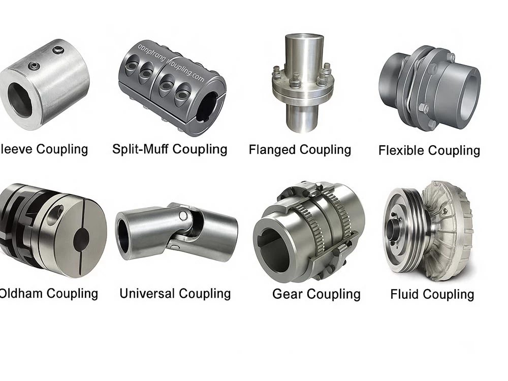
Rigid couplings are best when shafts are accurately aligned and rigidity is the priority. Flexible couplings are used when you need misalignment tolerance, vibration damping, or protection from shock loads.
Rigid vs. Flexible Couplings Comparison Table
| Feature | Rigid Coupling | Flexible Coupling |
|---|---|---|
| Misalignment tolerance | Very low (near-zero) | Medium to high (depends on type) |
| Vibration damping | Minimal | Often good to excellent |
| Torque capacity | Very high | High (varies by design) |
| Backlash | Typically zero | Can be zero (bellows/diaphragm/disc) or higher (jaw/grid) |
| Cost | Often lower | Often higher (precision types cost more) |
| Typical applications | Precision-aligned shafts, heavy torque, slow/steady loads | Pumps, motors, gearboxes, servo systems, misaligned installations |
Below are the most common rigid shaft coupling types and flexible options used in 2026 industrial design. For each type, you’ll find a quick definition, structure, pros/cons, and CNC material guidance.

Definition: A simple cylindrical sleeve that joins two shafts end-to-end using keys, pins, or set screws.
Structure: One-piece sleeve (or two-piece in some designs) fitted over both shaft ends.
Pros
Simple design, cost-effective
High torsional rigidity
Good for steady torque applications
Cons
Poor misalignment tolerance
Disassembly can be inconvenient
Not ideal for high-speed imbalance-sensitive systems
CNC material suggestions
Carbon steel or alloy steel for strength
Stainless steel for corrosion resistance
Consider protective shaft couplings metal finishes (black oxide, zinc plating, passivation) for harsh environments
Best for
Well-aligned drive lines, basic machinery, low-maintenance installations
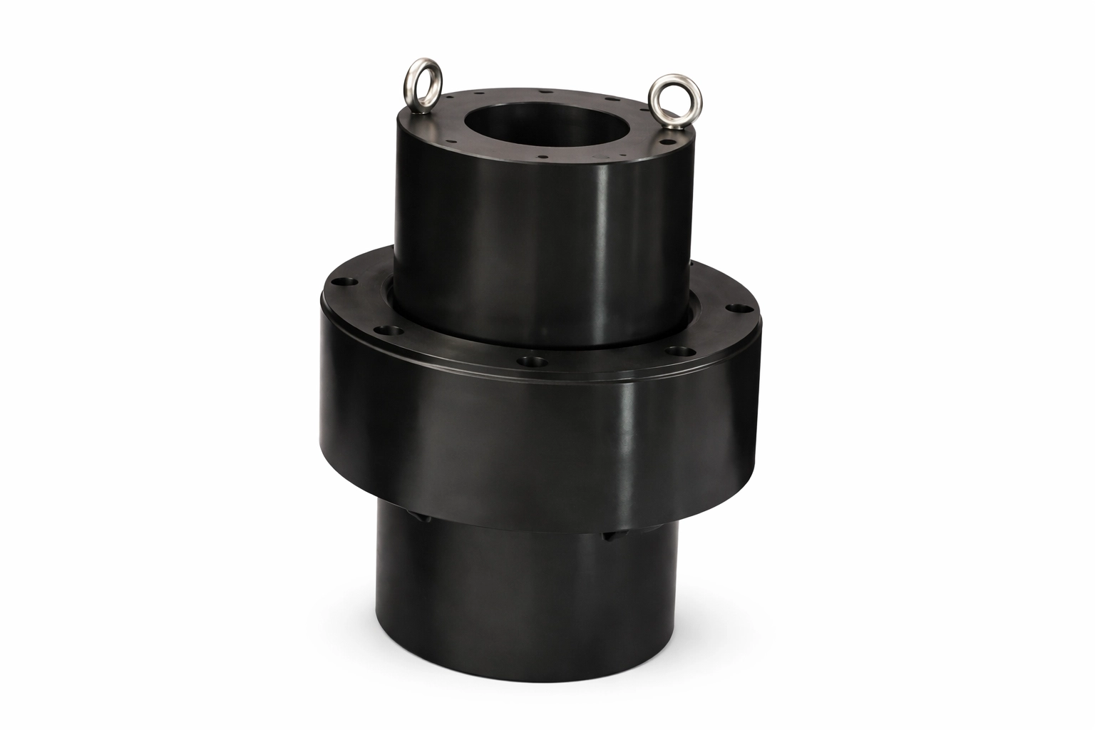
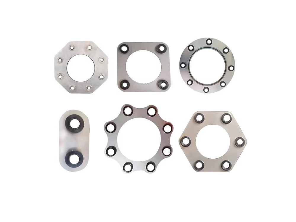
Definition: Two flanged hubs bolted together to connect shafts.
Structure: Two flanges + bolts (often keyed hubs).
Pros
Very high torque capacity
Easy to inspect bolts and interface
Strong and robust for heavy industrial loads
Cons
Needs good alignment (rigid)
Can transmit vibration directly
Higher mass; balancing may be required at speed
CNC material suggestions
Alloy steel for torque and fatigue strength
Stainless steel for chemical plants
Aluminum (only for lighter-duty systems)
Finishes: phosphate, nickel plating, anodizing (for aluminum)
Best for
Gearboxes, heavy pumps, large motors, high-torque drives
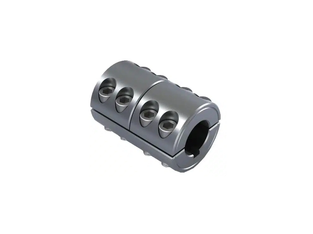
Definition: A rigid coupling split into two halves that clamp around the shafts.
Structure: Two-piece clamp body with bolts; often no key is needed depending on torque.
Pros
Easier installation/removal than a solid sleeve
Good holding power; strong for rigid connections
Great for maintenance-friendly designs
Cons
Still requires accurate alignment
Clamping bolts add diameter and weight
CNC material suggestions
Steel or stainless steel for industrial duty
Aluminum for lighter loads and easier handling
Precision-machined clamp bores improve repeatability
Best for
Equipment needing frequent assembly, test rigs, modular machinery
Learn more about the entire types of flexible couplings page here.
Definition: Two hubs with “jaws” and an elastomer spider in between to absorb shock.
Structure: Hub + spider + hub (elastomer insert).
Pros
Excellent shock absorption and vibration damping
Protects equipment from impact loads
Easy to assemble and service
Cons
Not always zero-backlash (depends on spider fit/design)
Elastomer can degrade with heat/chemicals
CNC material suggestions
Hubs: aluminum, steel, stainless
Spider: urethane, NBR, Hytrel (selection depends on temperature/chemicals)
Best for
Pumps, compressors, general motor drives, applications needing damping

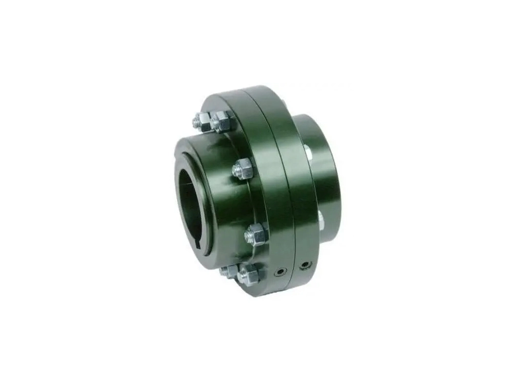
Definition: Uses external and internal gear teeth to transmit high torque with some misalignment capability.
Structure: Two hubs with gear teeth + sleeve with internal teeth; often lubricated.
Pros
Very high torque density
Good for heavy-duty industrial drives
Can handle some misalignment
Cons
Needs lubrication and periodic maintenance
More complex machining and assembly
Backlash can exist depending on tooth design
CNC material suggestions
Heat-treated alloy steel for wear resistance
Tooth accuracy and surface hardening matter
Finishes and coatings can help in corrosive environments (but tooth engagement must be compatible)
Best for
Steel mills, mining, large compressors, heavy conveyors
Definition: A flexible coupling that uses a spring-like metal grid to transmit torque while absorbing shock.
Structure: Two slotted hubs + serpentine grid + cover (often grease-lubricated).
Pros
Strong shock-load capability
Good vibration damping compared with rigid types
Reliable for industrial drives
Cons
Maintenance (lubrication/inspection)
Not the best for ultra-precision zero-backlash servo control
Bulkier than compact precision couplings
CNC material suggestions
Steel hubs, hardened grid elements
Proper groove machining is critical to load distribution
Best for
Pumps, fans, crushers, mixers—where impact loads happen
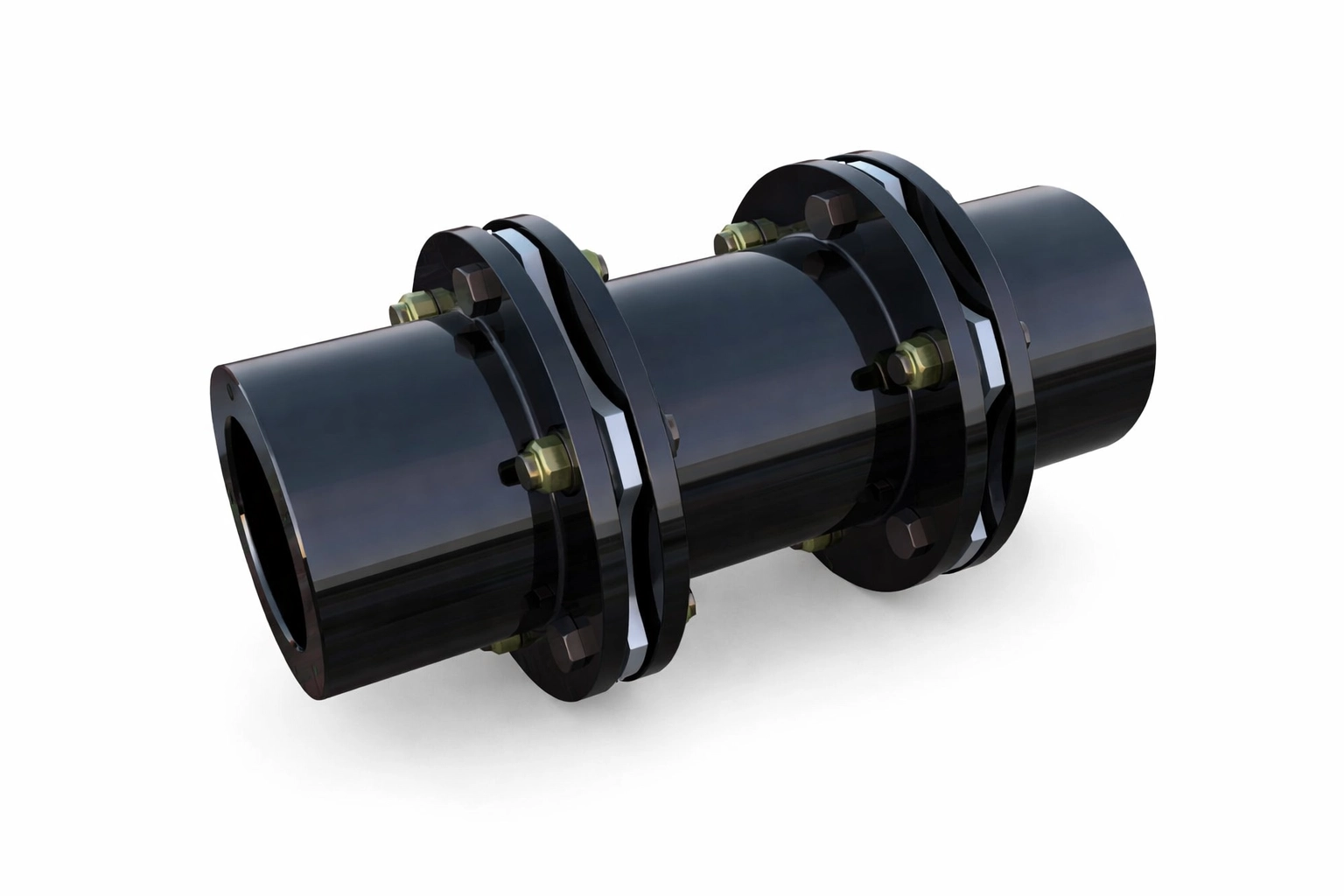
Definition: Uses pins with rubber or polymer bushes to allow flexibility and damping.
Structure: Flanged hubs connected by pins + elastomer bushes.
Pros
Good vibration isolation and shock absorption
Tolerates moderate misalignment
Simple maintenance (replace bushes)
Cons
Bushes wear over time
Not ideal for very high-speed precision systems
CNC material suggestions
Hubs: steel or cast steel
Bushes: rubber, polyurethane (chemistry/temperature dependent)
Best for
Medium-duty industrial drives with moderate misalignment and shock
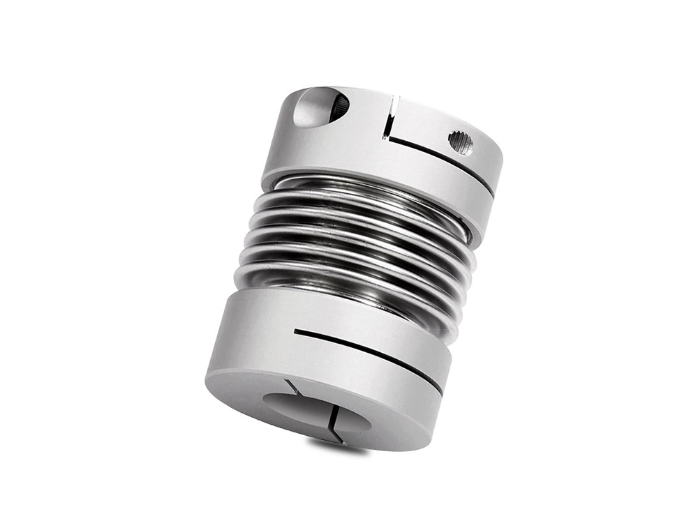
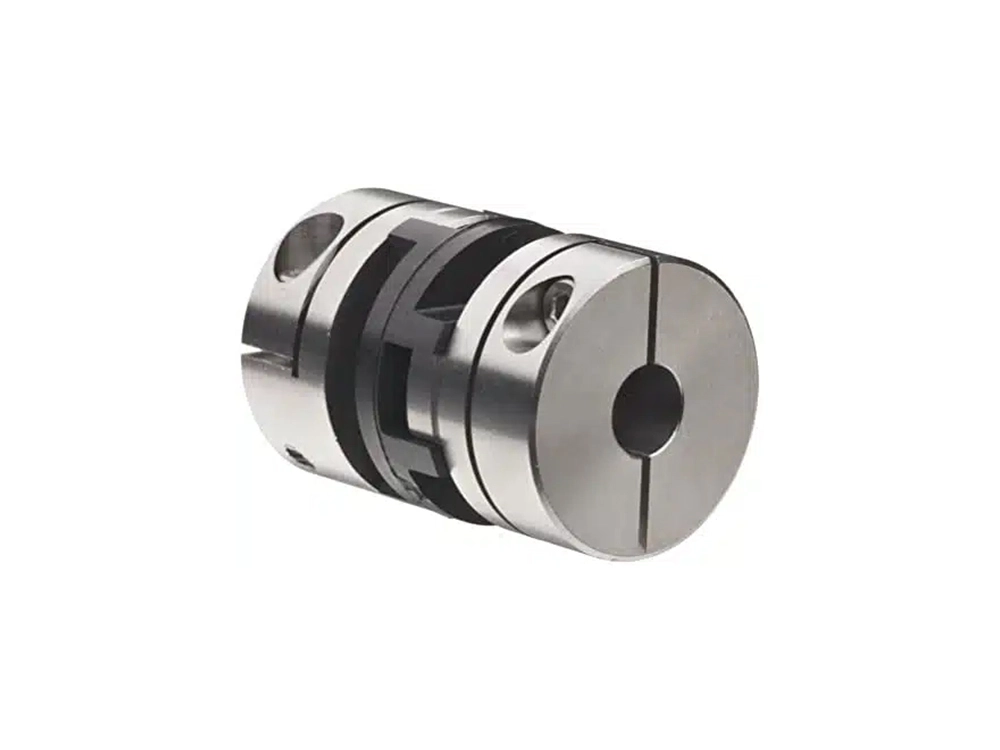
Definition: A high-precision flexible coupling using a thin-walled metal bellows to provide torsional stiffness with misalignment capability.
Structure: Hub + metal bellows + hub (often welded or brazed).
Pros
Zero backlash (ideal for servo)
High torsional rigidity (excellent motion fidelity)
Handles angular/axial misalignment within limits
Cons
Lower shock-load tolerance than jaw/grid
More sensitive to overload
Higher cost due to precision manufacturing
CNC material suggestions
Bellows: stainless steel (common), sometimes special alloys
Hubs: aluminum or stainless steel
Tight tolerance bores and high concentricity improve performance
Best for
CNC/servo motion control, robotics, encoders, precision automation
Definition: Uses one or more metal diaphragms to transmit torque while flexing for misalignment.
Structure: Hub + diaphragm pack(s) + hub (bolted assembly).
Pros
High torque capacity with low backlash
Good for high speed (with balancing)
Handles angular and axial misalignment well
Cons
Less damping than elastomer couplings
Diaphragm fatigue if misalignment is excessive
Requires careful bolt torque control
CNC material suggestions
Diaphragms: stainless steel (fatigue + corrosion resistance)
Hubs: steel/aluminum depending on torque and inertia targets
Surface finishes: passivation/electropolish for corrosion environments
Best for
Turbomachinery, compressors, precision drives requiring stiffness
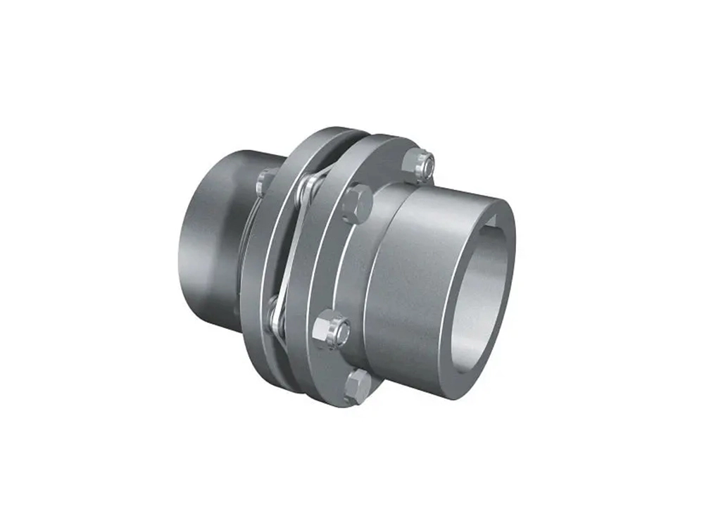
Definition: Similar to diaphragm style; torque transmits through thin disc packs that flex under misalignment.
Structure: Two hubs connected via one or two stainless disc packs and spacers.
Pros
Can be zero backlash
High torsional stiffness for control systems
High-speed capable (balanced designs)
Cons
Minimal damping (can transmit vibration)
Disc fatigue if misalignment is too high
More expensive than basic flexible couplings
CNC material suggestions
Disc packs: stainless steel
Hubs: aluminum (low inertia) or steel (high torque)
Precision machining for bolt circles, flatness, and balance
Best for
Servo systems, indexing, pumps/compressors needing precision
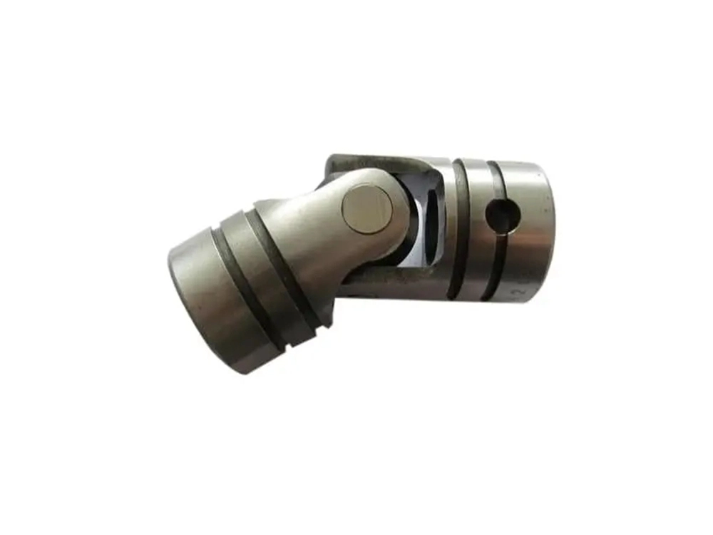
Definition: A mechanical joint that transmits torque through angled shafts, commonly called a u joint shaft coupling.
Structure: Cross-shaped trunnion + yokes + needle bearings (or bushings).
Pros
Handles large angular misalignment
Robust for steering shafts, driveline systems, articulating machinery
Cons
Speed fluctuation at angles (single U-joint)
Wear in bearings if not lubricated/maintained
Not ideal for ultra-precision motion without careful design
CNC material suggestions
Alloy steel yokes, heat-treated cross components
Protective coatings for corrosion; ensure bearing compatibility
Best for
Off-axis drives, steering systems, agricultural machinery, articulated transmissions
Definition: Uses a center disc that slides in orthogonal grooves to handle parallel misalignment.
Structure: Hub + floating center disc + hub.
Pros
Excellent for parallel misalignment
Can be low backlash with proper disc fit
Electrically isolating options (plastic center)
Cons
Center disc wears over time (especially at high speed)
Torque capacity is moderate
Not ideal for heavy shock loads
CNC material suggestions
Hubs: aluminum/steel
Center disc: acetal (POM), nylon, PEEK (for higher performance)
Best for
Light-to-medium servo applications, instruments, printers, automation modules
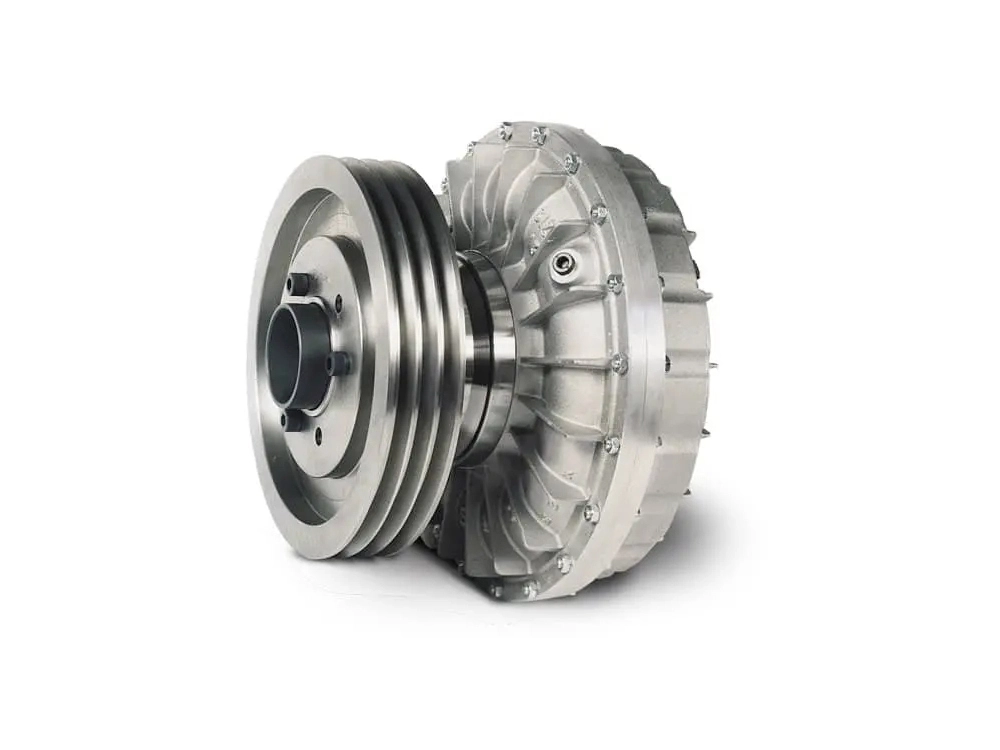
Definition: A hydrodynamic coupling that transmits torque through fluid (often oil), enabling smooth starts and overload protection.
Structure: Pump impeller + turbine runner + housing filled with fluid.
Pros
Smooth start-up reduces shock and current spikes
Protects drivetrain under overload
Good for heavy inertia loads
Cons
Not a rigid/precision connection (slip is inherent)
Efficiency loss due to slip
Larger size and more complexity
CNC material suggestions
Housing and impellers often use cast/forged metals with precision-machined interfaces
Seal and balance quality are critical
Best for
Conveyors, crushers, heavy fans, applications needing soft-start torque control
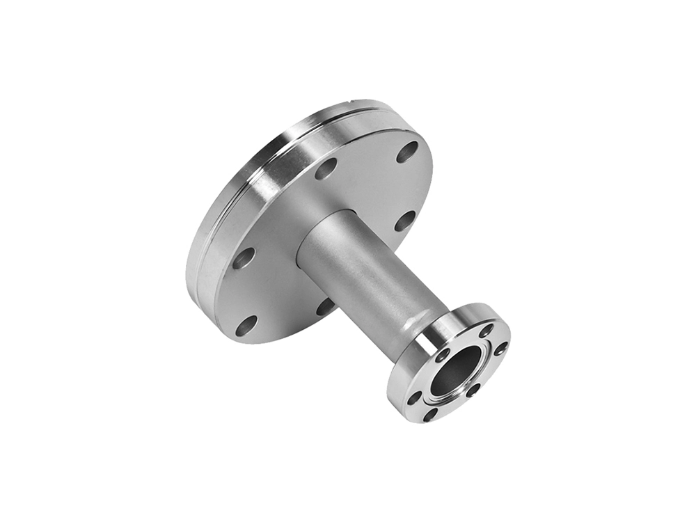
When people search “mechanical coupling,” they often mean shaft couplings—but piping systems also rely on mechanical couplings and connectors for fast installation, maintenance access, and leak control. This is where CNC machining can add major value through tighter tolerances, better sealing surfaces, and repeatable clamp geometry.
Mechanical Joint Pipe Fittings & Connectors
Mechanical joint pipe fittings are designed to connect pipe sections using mechanical compression, bolts, gaskets, or clamp-style connectors. Common related searches also include pipe connector clamp and clamp-style pipe connectors for repairs and retrofits.
Where they shine:
Repairs where welding is not practical
Installations requiring easy disassembly
Industrial fluid transfer lines (water, oil, chemicals—material dependent)
Note on “rubber coupler” searches:
Many users also look for rubber couplers by size/brand. For example, “3 fernco coupling” is a common way people search for a 3-inch rubber plumbing coupler used in drainage/vent and repair connections (always confirm compatibility with your pipe material, code requirements, and temperature/chemical exposure).
Piping reliability isn’t just about joining pipe ends—support and sealing matter too:
Metal pipe clamp: used to secure pipes to structures and reduce vibration movement
Horizontal pipe support brackets: provide consistent load distribution and alignment along runs
Rubber plumbing coupler: provides flexible sealing and vibration isolation (often used in repairs)
Use this quick framework to select the best mechanical coupling for your system.
High torque, low speed: flange, gear, grid couplings
High speed: disc/diaphragm/bellows (balanced), some gear couplings (with proper lubrication and balance)
Soft-start/heavy inertia: consider fluid coupling
Tip: If the application is high RPM, pay attention to hub mass, balance grade, and clamping method.
Misalignment typically falls into:
Parallel (offset) misalignment
Angular misalignment
Axial (end float) misalignment
General matching:
Parallel misalignment: Oldham excels
Angular + axial (precision): bellows, diaphragm, disc couplings
Larger misalignment with robustness: jaw, grid, bush pin
Extreme angle: u joint shaft coupling
Material and surface engineering matters as much as geometry:
Corrosion/wet/chemical: stainless steel + passivation/electropolish
Lightweight and corrosion-resistant: aluminum + anodizing
Electrical isolation: engineered plastics (POM/PEEK) or elastomer inserts
Abrasive/dirty environments: choose designs that tolerate contamination and allow maintenance
This is where CNC machining materials selection (stainless, aluminum, brass, high-performance plastics) and shaft couplings metal finishes (anodizing, zinc plating, nickel plating, black oxide, passivation) can extend service life dramatically.
If you’re building a precision motion system (servo/CNC/robotics):
Aim for zero-backlash: bellows, disc, diaphragm couplings
Avoid high-compliance designs if positioning accuracy is critical (unless damping is more important than precision)
Off-the-shelf couplings work for many applications—but if you’re optimizing performance, space, or reliability, custom machining can be the difference between “works” and “works for years.”
At Chiheng Hardware, precision CNC machining supports complex coupling components such as:
Flange couplings with controlled bolt circle runout
Rigid clamp couplings with accurate split geometry and consistent clamping force
Bellows coupling hubs and precision interfaces where concentricity and balance matter
Material coverage (typical custom options):
Steel (strength, fatigue resistance)
Aluminum (low inertia, corrosion resistance with anodizing)
Brass (special corrosion and compatibility cases)
High-performance plastics (lightweight, isolation, chemical resistance)
Common value-add processes:
Tight-bore tolerances for slip-fit or clamp-fit assemblies
Balancing features for high RPM
Durable shaft couplings metal finishes for corrosion and wear protection
In the production of mechanical couplings, precision and material handling are critical. Common manufacturing methods include casting for complex shapes, forging for high-strength parts like gear teeth, and machining techniques such as turning, milling, and drilling for achieving accurate fits. Among these, CNC machining and programming play a pivotal role in ensuring consistency and high precision, especially for components requiring tight tolerances and repeatability. With advanced CNC systems, manufacturers can efficiently produce custom couplings tailored to specific industrial needs, improving both performance and reliability in real-world applications.