
DXF File Preparation Guide for CNC Machining and Laser Cutting
Preparing a DXF (Drawing Exchange Format) file is an essential step in CNC machining, bridging design and manufacturing by providing precise, vector-based blueprints for processes like laser cutting, milling, and engraving. By ensuring proper scaling, clean geometry, and organized layers, DXF files enable efficient toolpath generation, minimize errors, and support versatile applications across industries such as metal fabrication, architectural design, and prototyping.
Creating DXF Files - CAD to DXF Conversion
DXF (Drawing Exchange Format) files are widely used in CAD and CNC machining for their ability to store vector graphic data. Here's an overview of key aspects of DXF file preparation and formatting:
| Aspect | Details |
|---|---|
| File Type | Vector-based, uncompressed ASCII text |
| Common Software | AutoCAD, SolidWorks, Fusion 360 |
| Key Elements | Lines, arcs, polylines, coordinates |
| Preparation Tips | Use up to 16 decimal places precision |
| Compatibility | AutoCAD R12/R14 formats for legacy systems |
When preparing this vector blueprints, ensure all geometry is properly defined, remove unnecessary elements, and verify that units and scaling are correct. For CNC applications, organize cutting paths into appropriate layers and check that all contours are closed. Always verify the exported file in a separate program to confirm all required geometry is included and properly formatted.
Best Practices & Troubleshooting
Closed Polyline Standards
A closed polyline must be generated directly using the closure parameter. It is prohibited to manually connect endpoints with line segments (e.g., when drawing a triangle with a polyline, use the "Close (C)" option instead of manually joining the endpoints). The closure operation must meet the following conditions:
- • When using the PE or PEDIT command, at least two segments must be drawn to activate the closure function.
- • If the line width is greater than 0, the closure command must be used to avoid gaps.
- • Use the properties panel (Ctrl+1) to check the "Closed" attribute to ensure the system recognizes it as closed.
Graphic Integrity Control
- • When using the JOIN command to merge endpoint-connected segments, avoid generating duplicate or overlapping lines.
- • Surface processing elements should use a single closed polyline, and adjacent closed polylines must have fully coincident shared edges.
- • It is recommended to use the OFFSET command to create new polylines instead of copying overlapping lines.
Common Issue Solutions
Fixing Unclosed Polylines
Issue: The properties panel displays "Not Closed."
Solution:
- a. Execute PE → Select the polyline → Enter J to merge endpoints.
- b. If the endpoint gap is too large, drag the endpoints to coincide before closing again.
- c. For complex graphics, use the BOUNDARY command to generate a closed polyline automatically.
Handling Overlapping Lines
Issue: Duplicate lines, jagged lines, or unclosed areas appear.
Solution:
- a. Use the OVERKILL command to delete duplicate segments.
- b. For non-parametric closed polylines, execute EXPLODE → PEDIT → Close again.
- c. Adjacent closed polylines must have fully overlapping shared edges; use the STRETCH command to adjust if necessary.
Special Case Handling
- • Hatch Pattern Failure: Ensure the boundary consists of a single closed polyline and avoid pseudo-closures formed by arcs or line segments.
- • 3D Conversion Issues: Closed polylines must not be self-intersecting; use the FLATTEN command to reduce dimensions if needed.
- • Line Width Display Issues: Check if the FILLMODE system variable is set to 1 to ensure wide-line fill mode is enabled.
Vector Blueprints in CNC Workflow
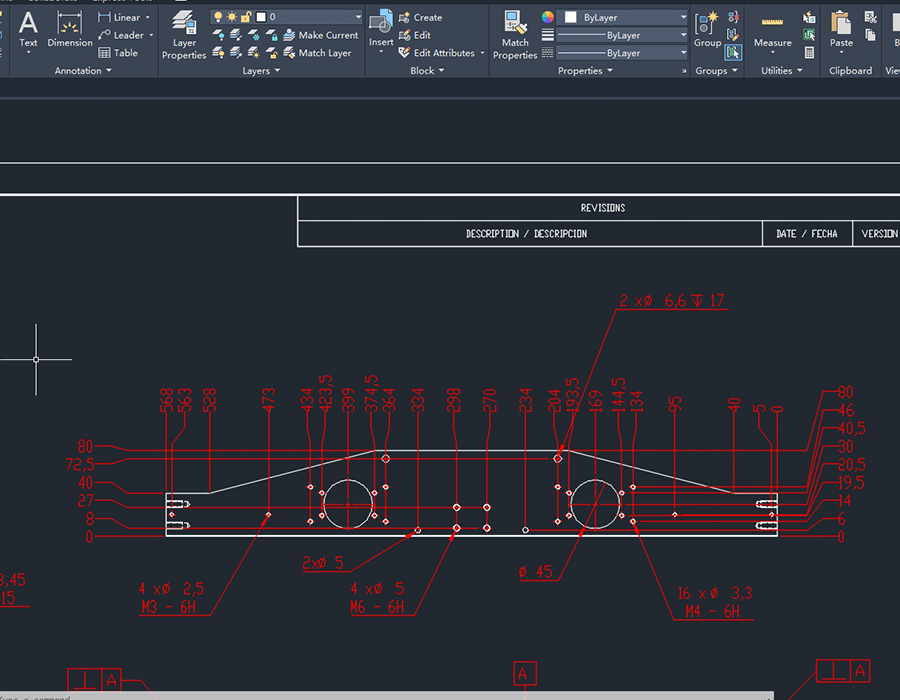
DXF File Formats: 2D
A 2D DXF file format is a CAD data file that contains two-dimensional vector graphics including lines, circles, text and other flat geometric entities.
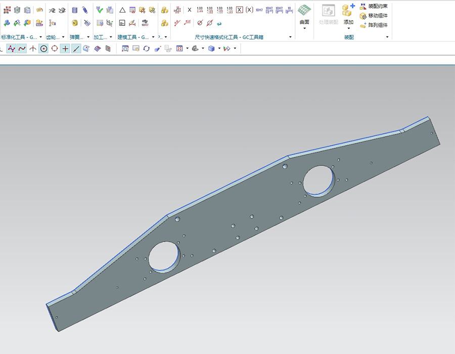
DXF File Formats: 3D
A 3D DXF file format extends the standard DXF to include three-dimensional model data with depth information, surfaces and solids
Vector blueprints play a crucial role in the CNC (Computer Numerical Control) workflow, serving as a bridge between design and manufacturing. These files act as digital blueprints, guiding CNC machines to perform precise cutting, drilling, milling, or engraving operations.
In the CNC process, the files are typically imported into CAM (Computer-Aided Manufacturing) software, which interprets the geometry and generates toolpaths for the machine. This seamless integration enables efficient translation of design concepts into machine-ready instructions, simplifying communication between designers and machinists
Key advantages of using DXF files in CNC workflows include:
- • Versatility in applications, supporting various CNC processes like laser cutting, plasma cutting, and milling
- • Ease of use for toolpath creation, as CAM software can directly translate DXF geometry into machine instructions
- • Ability to handle both simple and complex CAD drawings, preserving intricate details during file exchange
- • Improved collaboration and productivity through streamlined data transfer across different CAD systems
- • Cost-effectiveness by reducing the need for manual drafting and minimizing material waste through optimized cutting patterns
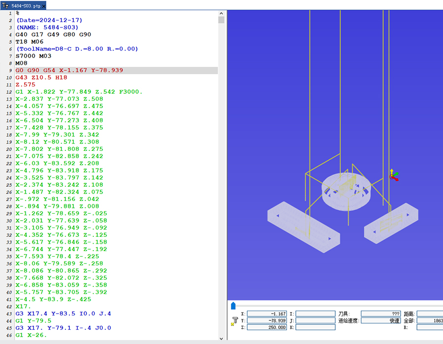
DXF to G-Code Conversion
Converting DXF files to CNC programs involves translating vector graphics into machine-readable G-code. This process typically requires Computer-Aided Manufacturing (CAM) software to interpret the DXF geometry and generate toolpaths. Popular CAM options include Fusion 360, MasterCAM, and open-source alternatives like CAMotics. The conversion process generally involves these steps:
- • Import the DXF file into CAM software
- • Define machining parameters (tool selection, cutting depths, speeds)
- • Generate toolpaths based on the DXF geometry
- • Post-process the toolpaths into G-code compatible with your specific CNC machine
For simpler 2D designs, some CNC controllers offer "conversational" programming that can directly interpret DXF files without separate CAM software. However, for complex 3D parts or advanced machining operations, dedicated CAM software provides greater control and optimization capabilities.
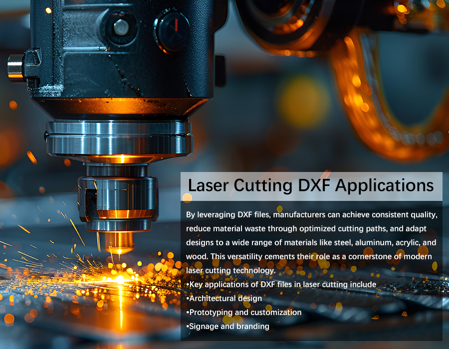
Laser Cutting DXF Applications
DXF files are indispensable in CNC laser cutting, offering unmatched precision and efficiency for a variety of applications. These vector-based files store 2D and 3D drawings, which are directly interpreted by CNC machines to create detailed cuts with minimal error. Key applications of DXF in laser cutting include:
- •Used extensively in industries like automotive and aerospace to produce high-precision components such as engine parts and lightweight structural elements.
- • Architectural design: Enables the creation of intricate decorative panels, custom installations, and artistic metalwork for interiors and exteriors.
- • Prototyping and customization: Facilitates rapid production of prototypes or personalized products by allowing quick modifications to designs without extensive retooling.
- • Signage and branding: Supports the production of detailed logos, lettering, and custom signs for commercial use.
By leveraging the vector files, manufacturers can achieve consistent quality, reduce material waste through optimized cutting paths, and adapt designs to a wide range of materials like steel, aluminum, acrylic, and wood. This versatility cements their role as a cornerstone of modern laser cutting technology.
To check the units of a DXF file in AutoCAD, you can:
- Use the DWGUNITS command: Open the DXF file in AutoCAD, type DWGUNITS in the command line, and press Enter.
- Inspect the DXF header manually: Open the file in a text editor and search for $INSUNITS or $MEASUREMENT.
- Check via AutoCAD interface: Go to Application Menu > Drawing Utilities > Units.
For CNC milling machines, the AutoCAD 2007 DXF format is widely recommended due to:
- Stability: Broad compatibility with CAM software.
- Toolpath compatibility: Ensure clean 2D geometry without unnecessary layers or 3D elements.
- Troubleshooting: If issues arise, try exporting to other versions (e.g., R12/LT2 DXF).


